background image

9

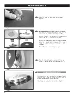
Fig.23

Fig.24

Fig.25

MAINTENANCE

EQUIPMENT

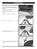
Wheel replacement

For proper machine operation, inspect the wheels for
wearing and to ensure the working angle is not altered
as the wheels wear down. 

The proper working angle is necessary to maintain:
- Adequate dust suction
- proper sanding finish

Replace wheels as required to maintain the proper
working angle.

Dust suction

The machine is equipped with a dustbag.  For
optimum performanc:

1

The working angle should be the adequate. A tilted
machine is not able to vacuum properly.

2

Empty the dustbag when it is 1/3 full. Suction
becomes less effective when the bag gets too full.

3

Do not use the machine with more than one disk of

sandpaper.

4

The bag is made with a special material which lets
air through, but not dust.

5

Change the dustbag several times a year, even if it
is not torn; the aging of material due to dust
accumulation will obstruct the air circulation and
therefore cause faulty suction.

Tool bag

A tool bag with wrenches is provided for machine
maintenance. 

Summary of Contents for SD70

Page 1: ...IONS YOU HAVE JUST ACQUIRED A HIGH QUALITY SANDER PLEASE READ THIS MANUAL CAREFULLY BEFORE OPERATING YOUR NEW SANDER KEEP MANUAL ON HAND FOR FURTHER REFERENCES TECHNICAL MACHINE SPECIFICATIONS Single...

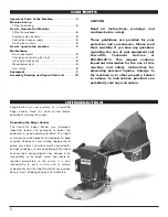
Page 2: ...nstructions for preventing personal injuries damage to the machine or to other property Failure to adhere to instructions provided can potentially void any warranties INTRODUCTION Congratulations on y...

Page 3: ...he motor and the OFF to stop Suction dust tube The suction dust tube is placed at the back of the machine next to the dustbag holder Dustbag The dustbag must be clipped to the suction tube and its hol...

Page 4: ...tube 2 Fit the dustbag holder 3 Fit the dustbag 1 Sandpaper discs with an adhesive backing use 178 mm disks and simply place the sandpaper disk on the sanding disk Fig 6 2 Sandpaper discs with a pape...

Page 5: ...st be in perfect condition 1 Before connecting the cord to the power supply make sure that the switch is in the 0 position 2 Place the machine in a vertical position and tilted backward 3 Hold the mac...

Page 6: ...hen working The brushes and their housing should be cleaned using compressed air Inspect brushes on a regular basis They should be replaced before the automatic disconnection stops the machine This wi...

Page 7: ...high speed motors needs a regular replacement of the belt 1 For adjusting or replacing the belt disconnect the power supply 2 Loosen both screws without removing them Fig 15 3 Loosen the nut without...

Page 8: ...the pulley track where the belt slides Fig 22 7 Remove the guard which covers the central screw with a screwdriver Holding the disk with one hand ease the central screw with an Allen wrench Fig 20 a...

Page 9: ...For optimum performanc 1 The working angle should be the adequate A tilted machine is not able to vacuum properly 2 Empty the dustbag when it is 1 3 full Suction becomes less effective when the bag g...

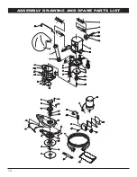
Page 10: ...10 ASSEMBLY DRAWING AND SPARE PARTS LIST...

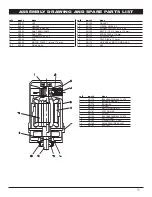
Page 11: ...RING OR 90 X 3 32 SD168 SCREW DIN 7991 M 10 x 40 41 SD169 BELT Z 19 3 4 disc 178 mm 43 SD170 STEEL DISC 178 mm 45 SD172 CONICIAL NUT 46 SD173 FELT DISC 178 mm 47 SD174 UNIVERSAL MOTOR MOG USA 57 SD17...

Page 12: ...s warranty is in lieu of all other warranties expressed or implied and releases Powr Flite from all other obligations and liabilities Powr Flite assumes no responsibility for repairs and the costs of...

Reviews: