Chapter 5 Function parameter
32
Ch
ap
ter 5
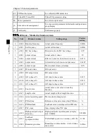
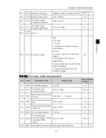
5-1-3.
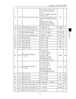
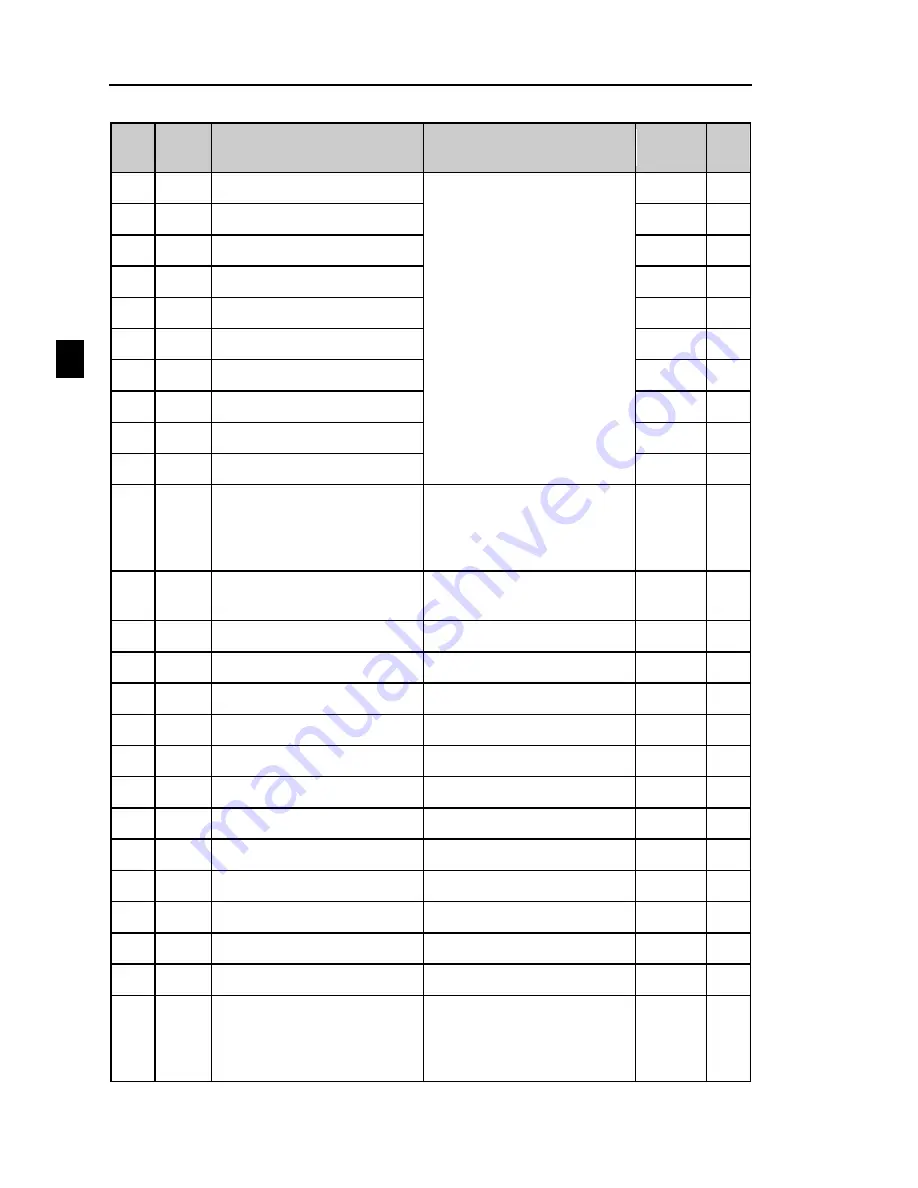
F1 Group - Input terminals group
No.
Code
Parameter name
Setting range
Factory
setting
Chan
ge
70.
F1.00 DI1 terminal function selection
0 to 51
1
★
71.
F1.01 DI2 terminal function selection
2
★
72.
F1.02 DI3 terminal function selection
0
★
73.
F1.03 DI4 terminal function selection
9
★
74.
F1.04 DI5 terminal function selection
12
★
75.
F1.05 DI6 terminal function selection
13
★
76.
F1.06 DI7 terminal function selection
0
★
77.
F1.07 DI8 terminal function selection
0
★
78.
F1.08 Undefined
79.
F1.09 Undefined
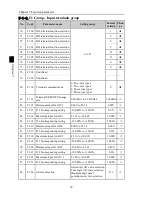
80.
F1.10 Terminal command mode
0: Two-wire type 1
1: Two-wire type 2
2: Three-wire type 1
3: Three-wire type 2
0
★
81.
F1.11
Terminal UP/DOWN change
rate
0.001Hz/s to 65.535Hz/s
1.000Hz/s
☆
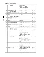
82.
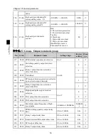
F1.12 Minimum input for AIC1
0.00V to F1.14
0.00V
☆
83.
F1.13 F1.12corresponding setting
-100.00% to +100.0%
0.0%
☆
84.
F1.14 Maximum input for AIC1
F1.12 to +10.00V
10.00V
☆
85.
F1.15 F1.14corresponding setting
-100.00% to +100.0%
100.0%
☆
86.
F1.16 Minimum input for AIC2
0.00V to F1.18
0.00V
☆
87.
F1.17 F1.16corresponding setting
-100.00% to +100.0%
0.0%
☆
88.
F1.18 Maximum input for AIC2
F1.16 to +10.00V
10.00V
☆
89.
F1.19 F1.18corresponding setting
-100.00% to +100.0%
100.0%
☆
90.
F1.20 Minimum input for AIC3
-10.00V to F1.22
0.00V
☆
91.
F1.21 F1.20corresponding setting
-100.00% to +100.0%
0.0%
☆
92.
F1.22 Maximum input for AIC 3
F1.20 to +10.00V
10.00V
☆
93.
F1.23 F1.22corresponding setting
-100.00% to +100.0%
100.0%
☆
94.
F1.24 AIcurve selection
Units digit: AI1 curve selection
Tens digit: AI2 curve selection
Hundreds digit:panel
potentiometer curve selection
321
☆

