14
12.2 - Power Supply
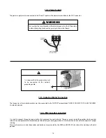
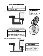
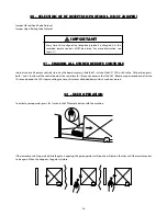
The power supply must be connected to the ‘R’ and ‘S’ inputs on the power terminal blocks, the CN7 Connector.
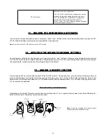
WARNING
Be sure that the circuit breaker in the electrical panel is in the OFF position
before attempting to connect any wiring to the control board.
It is required that the ground terminal
to be connected to the network
grounding cable.
12.3 - Induction Motor Connection
The three wires of the induction motor must be connected to the “MOTOR” terminal block. THERE IS NO NEED TO FOLLOW THE WIRES’
COLOR SEQUENCE3.
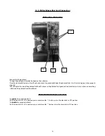
12.4 - ‘ENC’ encoder connection
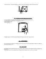
It is used to connect, through a proper cable, the motor and the control board. There are sensors inside the gearbox which provides
information on displacement direction and position of the gate during operation. Such information is essential to the operator’s proper
running.
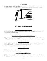
There are two sensors inside the encoder and each one is represented by the ENCA and ENCB LEDs. Each one lits according to the disk
position.
Summary of Contents for DZ 1500
Page 1: ...DZ PREDIAL DZ CONDOMINIUM DZ 1500 Technical Manual...
Page 2: ......
Page 30: ...30 26 REPAIR PARTS DZ PREDIAL JET FLEX 60HZ U...
Page 31: ...31...
Page 32: ...32 DZ CONDOMINIUM JET FLEX 60HZ U...
Page 33: ...33...
Page 34: ...34 DZ 1500 JET FLEX 60HZ Z12 U...
Page 35: ...35...


