29
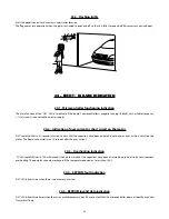
24.6 - Open end-of-stroke indication
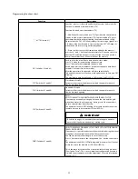
'FC' LED blinks when the gate is on an open end-of-stroke area.
24.7 - Close end-of-stroke indication
'FC' LED keeps lit when the gate is on a closed end-of-stroke area.
24.8 - Capacitor load indication
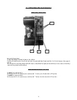
'BUS' LED indicates that the high voltages capacitors are charged. Do not touch them while this LED is ON (even when the control board
is disconnected from the power supply.
24.9 – Encoder Test
It is possible to test the operator's encoder; to do so; simply connect it to the control board and check if the 'ENCA' and 'ENCB' are
blinking when the operator runs. Each LED corresponds to a specific sensor; for example, 'ENCA' LED corresponds to the 'A' sensor inside
the gear motor.
24.10 - Thermal Protection
The operator has a thermal protection device that shuts off the motor when it reaches a temperature above 310 ºF.
The control board receiving two consecutive commands during this period, it will enter in hardshutdown mode (Audio alarm will
sound) and the operator will need to be reset.
For more information see topic 13.5.
25 - MAINTENANCE
On the table below, are cited some PROBLEMS - FAULTS, POSSIBLE CAUSES AND CORRECTION - which may occur in your operator.
Before any maintenance, the total disconnection from the mains is required.
TROUBLES / SOLUTIONS
FAIL
CAUSE
SOLUTION
The gate does not correspond to the
path of the place where the operator
has been installed (It breaks before it
reaches the stop or slams when closing).
There is an acquired path different from
the place where the operator has been
installed.
Press both '+' and '-' buttons at the
same time and keep them pressed until
'OSC' LED lits.
Gate keeps open and whenever it
receives opening commands, it closes.
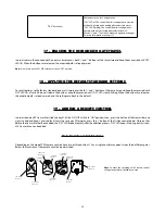
Acquiring was not properly performed.
Refer to item 'First operation after a
frequency inverter is installed on the
operator (Acquiring).
'OSC' LED blinks rapidly and the motor
turns itself off.
Current sensor activated. This may
happen when the motor has a
malfunction.
Check stator resistance. Check the
motor current (It must be less than
medium 3A RMS and 5A RMS peak
current (2s maximum)).
Summary of Contents for DZ 1500
Page 1: ...DZ PREDIAL DZ CONDOMINIUM DZ 1500 Technical Manual...
Page 2: ......
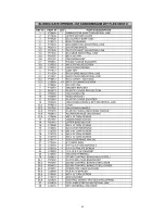
Page 30: ...30 26 REPAIR PARTS DZ PREDIAL JET FLEX 60HZ U...
Page 31: ...31...
Page 32: ...32 DZ CONDOMINIUM JET FLEX 60HZ U...
Page 33: ...33...
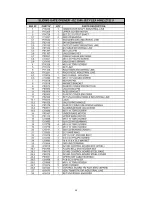
Page 34: ...34 DZ 1500 JET FLEX 60HZ Z12 U...
Page 35: ...35...

