10
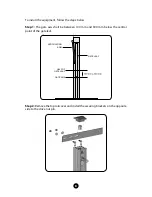
Step 6:
Position the automation vertically on the door column and weld the mounting
brackets on the column, respecting the measurements in the figure below.
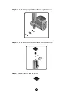
Step 7:
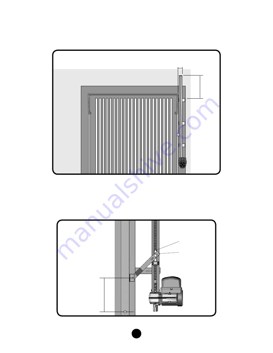
Attach the drive lever to the pin of the drive nut of the operator.
Step 8:
Weld the drive lever on the gate leaf, keeping the distance of 250 mm
between the center of the gate shaft and the center of the lever’s turning point.
110
mm
270 mm
TRIGGERING
NUT
TRACTION
LEVER
LEVER
TURNING POINT
250 mm
GATE AXIS


