background image

13

COMMAND BOARD:

Check the label attached to the 

product (according to the model 

on the side) which is the command 

board part of the operator. Once this 

is done, consult the board manual 

that is available for download at www.

ppa.com.br and make all connections 

and configurations.

illustr

ativ

e images

Code:

Model:

Reduction:

Technology:

Voltage:

Board:

Size:

Assembly:

Fairing:

Gear:

MAINTENANCE


In the table below, we will mention some PROBLEMS - DEFECTS, PROBABLE CAUSES 

AND CORRECTIONS - which may occur in your operator. Before any maintenance, it 

is necessary to completely disconnect the electricity.

DEFECTS

PROBABLE CAUSES

CORRECTIONS

Engine does not 

start / does not 

move

A) Power off

B) Open / burned fuse

C) Locked gate

D) Defective limit switch

A) Make sure that the power supply 

is connected correctly

B) Replace fuse with the same 

specification

C) Make sure that there is no object 

blocking the operation of the gate

D) Replace the limit switch system 

(analog and / or digital)

Motor blocked

A) Inverted motor connection

B) Blocked gate or trigger

A) Check the motor wires

B) Set to manual mode and check 

separately

Command board 

does not accept 

command

A) Fuse blown

B) Power line off (power)

C) Defect on remote control 

unloaded

D) Transmitter range (remote 

control)

A) Replace the fuse

B) Connect the power supply

C) Check and replace battery

D) Check the position of the 

receiver's antenna and, if necessary, 

reposition it to ensure the reach

Motor only turns 

to one side

A) Inverted motor wires

B) Inverted end-of-course system

C) Defect in the command center

A) Check the motor connection

B) Invert the limit switch connector 

(analog and / or digital)

C) Replace the board

Summary of Contents for POTENZA PREDIAL

Page 1: ...WARNING Do not operate the equip ment without first reading the instruction manual Technical Manual POTENZA PREDIAL BV...

Page 2: ...NS 3 TECHNICAL CHARACTERISTICS 4 TOOLS REQUIRED FOR INSTALLATION 5 ELECTRICAL INSTALLATION 5 PRECAUTIONS WITH THE GATE BEFORE INSTALLATION 7 FIXATION AND INSTALLATION OF THE OPERATOR 7 ANALOGIC LIMIT...

Page 3: ...n read and follow all instructions contained in this ma nual carefully Before installing the operator make sure that the local power supply is compatible with that required on the equipment iden tific...

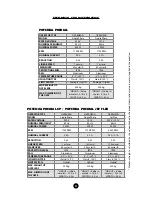
Page 4: ...Kg MAX DIMENSION OF THE GATE HEIGHT Value in meters 0 15 x 2 LENGTH 4 0 m HEIGHT Value in meters 0 15 x 2 LENGTH 4 0 m OPERATOR TYPE OVERHEAD OVERHEAD OVERHEAD MODEL Single Phase Single Phase Jet Fle...

Page 5: ...electrical distribution box 3 4 diameter conduit between the electrical distribution box and the total disconnect device 3 4 diameter conduit between the total shut off device and the automator s con...

Page 6: ...mm 500 V according to the norm NBR NM 247 5 The power conductor of a product for external use must be a flexible cable 3 x 0 75 mm 500 V according to IEC 60245 57 It is mandatory that the ground term...

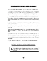
Page 7: ...near the button fixed control Check the manual release system fastened next to the actuation element of the unlocking Move the door leaf manually opening and closing and observe the required effort T...

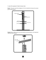
Page 8: ...1 The gate axis shall be between 100 mm and 300 mm below the central point of the gate leaf Step 2 Remove the top rail cover and install the securing brackets on the opposite side to the drive nut pin...

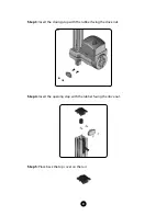
Page 9: ...9 Step 3 Insert the closing stop with the rubber facing the drive nut Step 4 Insert the opening stop with the rubber facing the drive nut Step 5 Place back the top cover on the rail...

Page 10: ...the figure below Step 7 Attach the drive lever to the pin of the drive nut of the operator Step 8 Weld the drive lever on the gate leaf keeping the distance of 250 mm between the center of the gate sh...

Page 11: ...with the gate open perform the same procedure for the opening stop ANALOGIC LIMIT SWITCH INSTALLATION Step 1 Position the limit switch magnet into the drive nut housing Position the opening and closin...

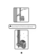
Page 12: ...12 Prior to the operation of the operator it is mandatory to screw the panel cover with 4 x 3 5 x 12 mm screws available in the kit PROTECTION RUBBER...

Page 13: ...limit switch A Make sure that the power supply is connected correctly B Replace fuse with the same specification C Make sure that there is no object blocking the operation of the gate D Replace the li...

Page 14: ...MOTOPPAR IND STRIA E COM RCIO DE AUTOMATIZADORES LTDA Av Dr Labieno da Costa Machado 3526 Distrito Industrial CEP 17400 000 Gar a SP Brazil www ppaamerica com 55 14 3407 1000 callcenter ppa com br...

Reviews: