3
FIGURES AND ILLUSTRATIONS
1. Schematic Diagram………………………………………………………
4
2. Operator Control Panel………………………………………………….
6
3. Safety Disconnect Switch...……………………………………………...
7
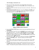
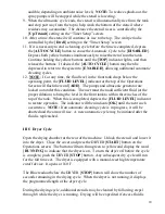
4. Operations Screen…………..……………………………………………
10
5. Fluid Temperature Screen…………………………………………….. .
13
6. Timer Setup Screen.……………………………………………………..
15
7. Operations Screen..……………………………………………………...
16
8. Manual Functions Screen ……………………………………….……..
18
9. Front Compartment…………………………………………………….
21


