19
INPUT : Jumper Settings
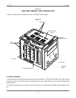
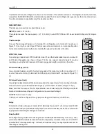
In addition to parameter settings, the Input Type selection also requires proper jumper settings. For the jumper settings; Pins &
Shorting-Link arrangement, marked ‘A’, is provided on the CPU PCB as shown in Figure 9.3.
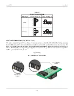
For DC Linear Current Inputs (0-20 mA or 4-20 mA), short the Pins 2 & 3 using Shorting-Link as shown in Figure 9.4 (b). For all
other Input types, short the Pins 1 & 2 using Shorting-Link as shown in Figure 9.4 (a).
Figure 9.4 (a)
For Input Types:
Thermocouples, RTD Pt100,
mV & V
1 2 3
Figure 9.4 (b)
For Input Types:
DC Linear Current (mA)
1 2 3
OUTPUT-1 : Jumper Settings
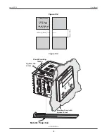
The Output-1 Type is user selectable as Relay or SSR through proper jumper settings. The jumper settings are provided as
Pins & Shorting Link arrangement (marked ‘B’ & ‘C’)
on Output PCB
,
as shown in Figure 9.3 and listed in Table 9.1.
Figure 9.3
User Manual
neuro 100EX
Shorting
Link
Pins
CPU PCB
1
2
3
A
1 2 3 4
C
1 2
3 4
Output PCB
Input
Jumper Settings
Output-1
Jumper Settings
Output-1
Jumper Settings
B

