22
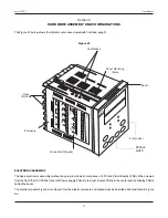
The Figure 9.5(a) shows the 4 & 5 Pin Female Sockets mounted on the
bottom side of the output modules. The Figure 9.5(b)
shows the 4 & 5 Pin Male Plugs Mounted on the CPU & Output PCBs. For clarity, the modules and the Power-Supply PCB are
not shown in the figure.
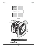
The Figure 9.6 shows the Output Modules fitted in their respective positions on the CPU & Output PCBs. For OP2, OP3 & OP4
modules; push the modules towards front for mounting and pull the modules towards back for removal. For OP5 module; push
the module towards right for mounting and pull the module towards left for removal.
(a) Relay / SSR Module
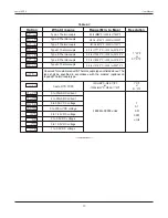
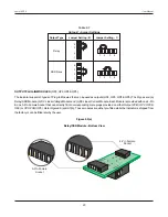
The Relay/SSR Module is supported by OP2, OP3 & OP4.The module can be configured to function as either Relay or SSR
Output by appropriate jumper settings, ‘A’ and ‘B’,as shown in Figure 9.7(a) & 9.7(b) and Table 9.2 below. Use
Shorting - Link
.
for jumper settings
Jumper Setting ‘A’ - Viewed facing module
Jumper Settiig-A
1 2 3
Figure 9.7(a)
Jumper Settiig-B
Jumper Setting ‘B’ - Viewed facing module
1 2 3
Figure 9.7(b)
User Manual
neuro 100EX
Table 9.2
Relay
SSR
Output Type
Jumper Setting - A
Jumper Setting - B
1
2
3
1
2
3
1
2
3
1
2
3

