User Manual
ScanLog 96 Pen Drive Version
28
Input Channels (Analog Input 1 & Analog Input 2)
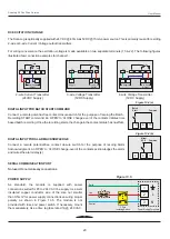
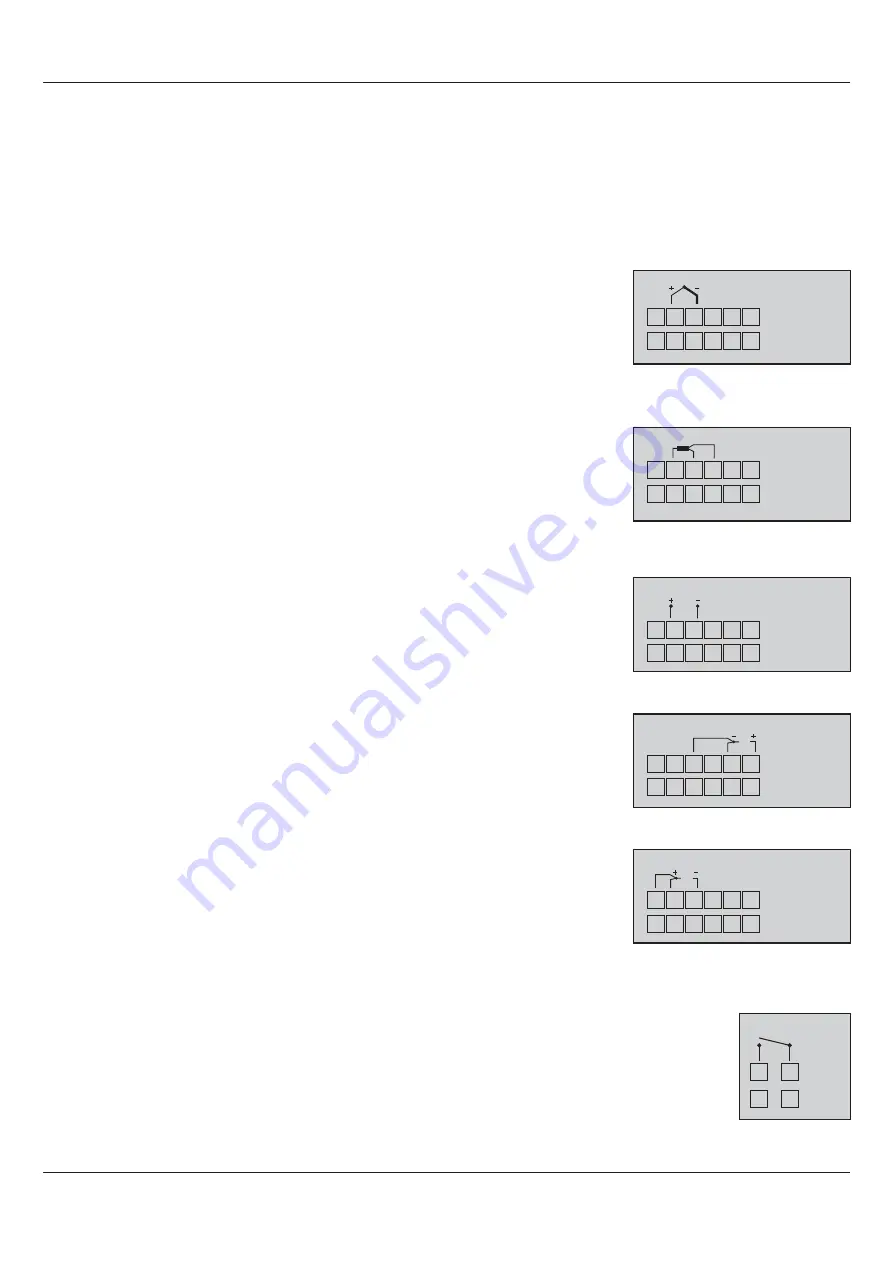
Channel 1 & Channel 2 are designed to interface with Thermocouples, RTD Pt100, mA, mV & V. The wiring connections for
each type are described below.
Thermocouple
Connect Thermocouple Positive (+) and Negative (-) as shown in
Figure 13.2(a)
.
Use the correct type of Thermocouple extension lead wires or compensating cable for the
entire distance ensuring the correct polarity throughout. Avoid joints in the cable.
DC Linear mV
Use a shielded twisted pair with the shield grounded at the signal source for connecting
mV source. Connect common (-) and the signal (+) wires as shown in
Figure 13.2(c).
RTD Pt100, 3-wire
Connect single leaded end and the double leaded ends of
RTD
bulb as shown in
Figure
13.2(b).
Double leaded connections are interchangeable for respective channel.
Use copper conductor leads of very low resistance ensuring that all 3 leads are of the
same gauge and length. Avoid joints in the cable.
Figure 13.2(b)
Figure 13.2(a)
TC
16 17 18 19 20 21
23 24 25 26 27 28
Analog Input 1
Analog Input 2
16 17 18 19 20 21
23 24 25 26 27 28
Analog Input 1
Analog Input 2
RTD
DC Linear V
Use a shielded twisted pair with the shield grounded at the signal source for connecting V
source. Connect common (-) and the signal (+) wires as shown. Also short terminals 18 &
20 for Channel 1 and terminals 25 & 27 for Channel 2, respectively. Refer
Figure 13.2(d).
DC Linear Current (mA)
Use a shielded twisted pair with the shield grounded at the signal source for connecting
mA source. Connect common (-) and the signal (+) wires as shown. Also short terminals
16 & 17 for Channel 1 and terminals 23 & 24 for Channel 2, respectively. Refer
Figure
13.2(e).
Figure 13.2(c)
Figure 13.2(d)
16 17 18 19 20 21
23 24 25 26 27 28
Analog Input 1
Analog Input 2
mV
16 17 18 19 20 21
23 24 25 26 27 28
Analog Input 1
Analog Input 2
V
Figure 13.2(e)
16 17 18 19 20 21
23 24 25 26 27 28
Analog Input 1
Analog Input 2
mA
ALARM OUTPUTS
Two Relay outputs, Relay-1 & Relay-2, are available as common Alarm Outputs. Relay-1 is common
Alarm-1 & Alarm-3 of all channels. Relay-2 is common Alarm-2 & Alarm-4 of all channels.
Relay contacts, N/O (Normally Open) & C (Common), are rated 2A/240 VAC (resistive load).
Figure 13.3
NO
4
5
C
6
7
Relay-1
Relay-2


