


5
Test Fit the Mounting Assembly
Option 1: Test fit the CSR and Mounting assembly in the conveyor
framework before doing the final installation . Place the CSR and Mounting
assembly in conveyor framework as shown in Figure 2 .4 .
Be sure the
travel direction and path of the wire and/or conduit is correct, and that the
set screws are accessible. The Smart Roll should be in the center of the
belt.
Check to make sure the roll is free to rotate and mounting arm is
free to pivot through its full range of motion . If there are any obstructions,
move the CSR and Mounting assembly out of the way and make the
necessary adjustments .
Option 2: Install both mounting brackets to the conveyor framework . One
bracket will be installed on each side of the belt with slots facing upward
and toward the center of the belt . Holes might be needed in the structure
for attaching the brackets .
Option 1 & 2: Move both collars to within 1/8 inch of CSR hinge and
tighten securely .
Final Installation of the Mounting Assembly
Option 1: Prepare the site for welding the ¾ inch diameter shaft to the
conveyor framework by providing adequate protection for the belt and
other components . Welding to be performed by qualified individuals
trained to AWS, or equivalent .
PPI is not capable of being aware of all site
specific and industry welding requirements for an application, and cannot
be held liable for non-compliant installations.
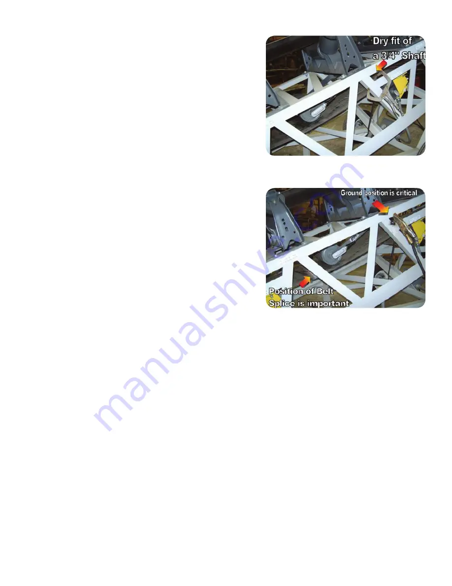
Proper weld ground location
is critical to prevent damage to bearings and sensor inside the Smart Roll .
These components will not tolerate welding current through them and will
be permanently damaged . Improper ground placement will void warranty .
Figure 2 .5 shows a typical welding set-up . Weld ground is placed in a
location keeping the flow of current away from the roll . Keep the belt
splice at least six inches away from the Smart Roll to further reduce the
chance of welding current damage .
When welding is completed remove welding protection, clamps, welding
ground, and any other objects used in installation . Clean weld area and
provide paint or other protective coating per accepted site practice .
Option 2: With the ¾ inch diameter rod installed in the CSR hinge, slide
the slots at the ends of the rod into the slots on the brackets . On each
end of the shaft install the teardrop shaped end clip over the end of the
shaft . Then install the screw into the hole in the end clip and bracket . This
is a self-threading screw; take care not to strip the threads on the screw
or the hole in the bracket .
FIGURE 2 .4: Test fit of CSR and Mounting Accessory assembly in
conveyor framework, typical both sides .
FIGURE 2 .5: Permanent attachment of 3/4 inch shaft to framework .
Component protection for welding has been removed for clarity .


