


O
UTDOOR ENCLOSURE TYPE
MINI
HANDBOOK
13
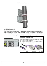
2.7
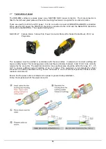
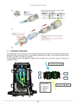
Termination of power
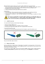
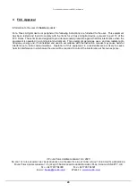
The ODE-MINI enclosure receives power via a NEUTRIK NAC3 power connector. The male connector is
fitted to the left hand gland plate and the cable mounting free female is supplied for on-site termination.
These are used for both AC and DC power. For AC connection connect LIVE/NEUTRAL/EARTH as labelled.
When used for DC power the POSITIVE should be connected to the LIVE and the NEGATIVE should be
connected to the NEUTRAL. The supplied mating half is:
NAC3FX-W
Female Black, Yellow 2P+E Power Connector Mains 20A Socket Cable Mount, 250 V ac
Polyamide.
This equipment must be earthed in accordance with the local codes. Incomplete or incorrect earthing will
cause a safety hazard. The incoming power cable must have a diameter between 6 and 12 mm to be correctly
retained by the connector. The electrical conductor cross sectional area should be within the range of 1 - 2.5
mm
2
to ensure sufficient current handling of up to 2 Amps. This equipment is not intended for direct
connection to building installation wiring; ensure connection is via an overcurrent protection breaker and/or
residual current device.
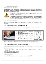
Ensure that the power cable is isolated and no power is present during installation.
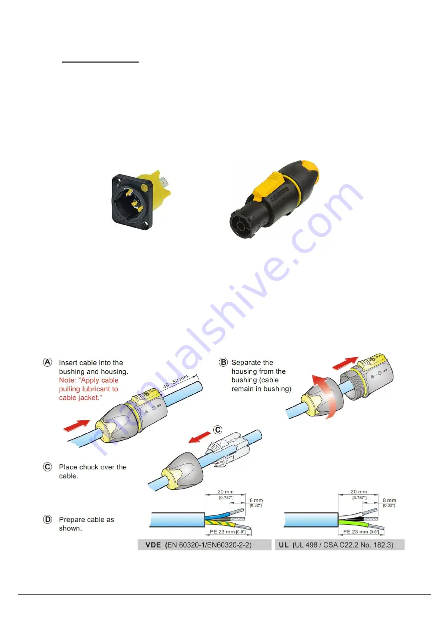
Follow the steps below to fit the power connector


