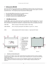


O
UTDOOR ENCLOSURE TYPE
MINI
HANDBOOK
5
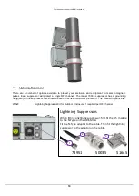
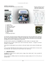
1.4
Fibre optic cable & connectors
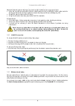
Connector and cable types
All
ViaLiteHD
RF modules use singlemode (9µm/125µm) cable terminated in a range of optical connectors
detailed below. Cross-site fibre optic cables are available from
ViaLite Communications
as either standard
patch leads or heavy-duty multicore cables.
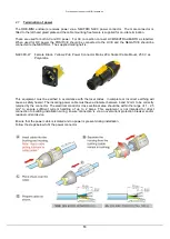
Warning!
Angle polished (APC) and standard (PC) connector must not be confused. The two
connector types are not interchangeable and mating one with the other will damage both the
cable and the module connectors.
The specification of optical connector is critical to the performance of the complete fibre optic
link. System performance can only be guaranteed with fibre optic cables and connectors
supplied by
ViaLite Communications
. When FC/APC connectors are specified they must
be “narrow key width”.
Connecting and disconnecting
Before connecting optical fibres to the module or to each other, ensure that the mating connectors are clean
(see below).
Cleaning optical connectors, cleaning before every use
Optical connectors MUST be cleaned before use, even where they have been protected with dust caps.
A large percentage of performance issues can be attributed to dirty fibres.
For more details please read the cleaning instruction which accompanies the connector cleaning kit.
Cleaning optical connectors, high levels of contamination
If there are performance issues that are not resolved by basic cleaning in section 1.4.3, then the following
procedure should be used. If the level of contamination is high it will be necessary to repeat this procedure.
Cleaning items required
Lint free fibre cleaning tissues and/or cleaning sticks (normal cosmetic tissues produce dust and are not
acceptable).
Reagent grade Iso Propyl Alcohol (IPA).
Air duster or filtered compressed air line.
Cable Connector Cleaning
Dampen a patch of cleaning tissue with IPA and clean all surfaces of the plug ferrule.
Using a dry cleaning tissue, dry the ferrule and clean the end face.
Using the air duster, blow away any residue from the end of the connector.
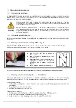
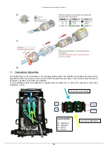
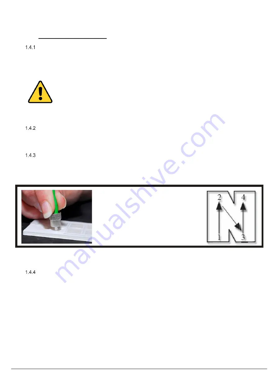
Peel the plastic cover from an unused “N”
cleaning pad.
Hold the connector between your thumb
and forefinger
Clean the connector using firm pressure by
swiping in a pendulum motion through each
segment of the “N” shape, following the
diagram
Do not swipe over the same space twice.