HRK3-HB-7
V
IA
L
ITE
HD
3U
CHASSIS
H
ANDBOOK
30
6.11.7
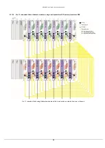
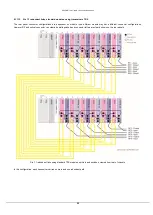
Six 1:1 redundant dual receivers, standard modules
The rear panel connector configurations are dependent on module type; different module may have different connector configurations.
However RF and optical connector can clearly be distinguished and connector letters are clearly shown on the rear panels.
Six 1:1 redundant receivers using standard plug in modules and switches, viewed from rear of the chassis
Top
– Connector configuration A (typically used with FC optical and SMA RF connectors)
Bottom - Connector configuration B (typically used with all other connector configurations)
6.11.8
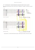
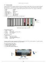
Six 1:1 redundant dual receivers, blindmate modules
Six 1:1 redundant receivers using blindmate plug in modules and switches, viewed from rear of chassis


