HRK3-HB-7
V
IA
L
ITE
HD
3U
CHASSIS
H
ANDBOOK
34
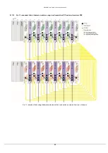
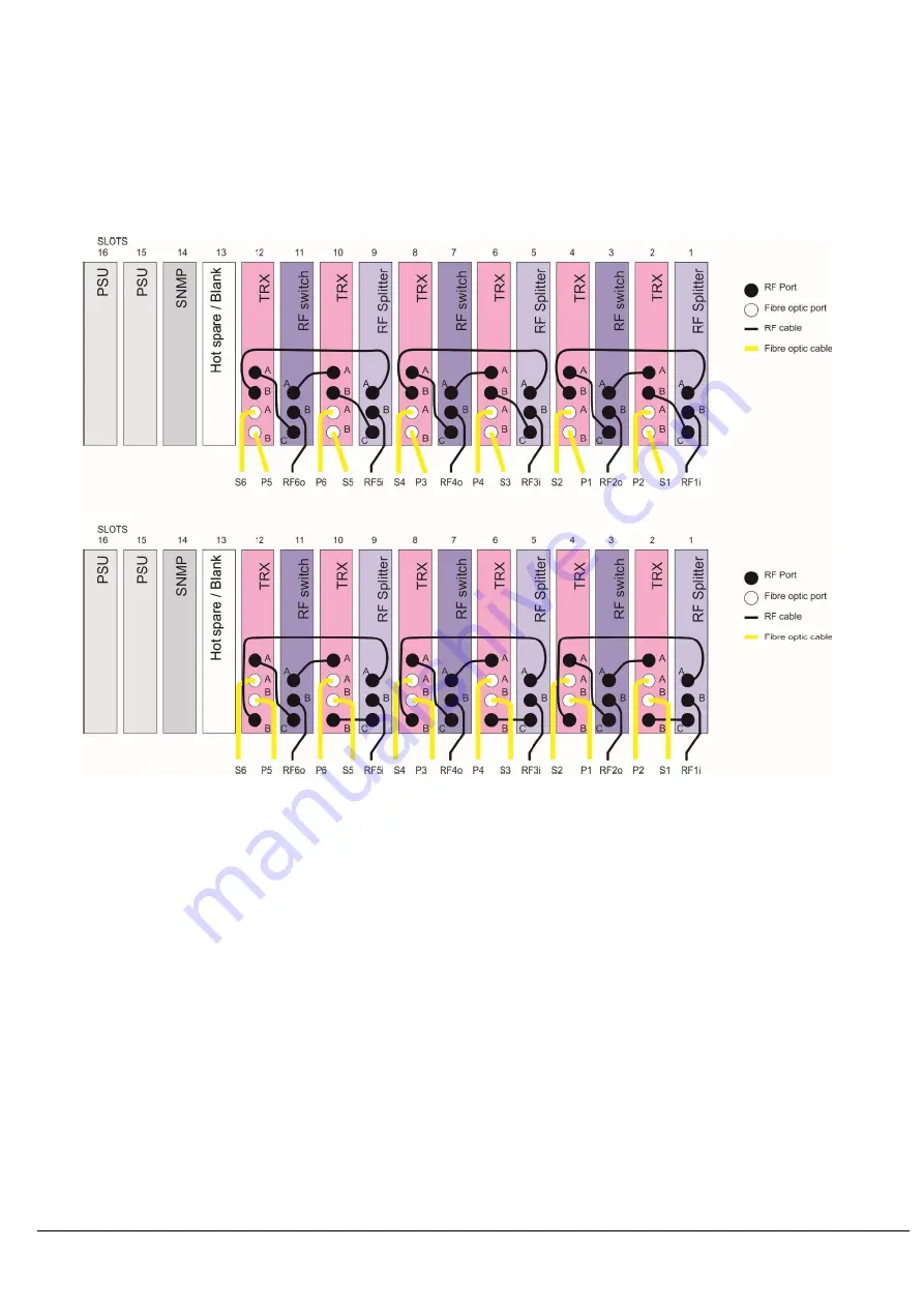
6.11.12 Six 1:1 redundant transceivers TRX, standard modules
This configuration should not be used for system that have LNA bias tee feed generated by the TRX transmitter (or fed through this module)
and that also require the DC bias to be switched by the RF splitter modules. The configuration below does not allow automatic switching of
the DC path via adjacent alarm sensing. If switching of the LNA bias feed is required use one of the previous configurations in sections
6.11.1 to 6.11.4
The rear panel connector configurations are dependent on module type; different module may have different connector configurations.
However RF and optical connector can clearly be distinguished and connector letters are clearly shown on the rear panels.
Six 1:1 redundant transceivers using standard plug in modules splitters and switches, viewed from rear of the chassis
Top
– Connector configuration A (typically used with FC optical and SMA RF connectors)
Bottom - Connector configuration B (typically used with all other connector configurations)


