HRK3-HB-7
V
IA
L
ITE
HD
3U
CHASSIS
H
ANDBOOK
7
4
ViaLiteHD System Components
4.1
ViaLiteHD
19” chassis
4.2
Description
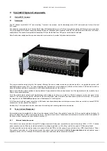
The 19” chassis is suitable for 19” rack mounting. There are two versions, one for alternating current (AC) power and one for direct current
(DC) power.
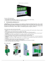
The chassis accommodates up to thirteen (5HP) plug-in RF/data modules, one (7HP) control module and two (6HP) plug-in power supplies.
The hot-swappable, dual power supply capability provides full redundancy and maximum reliability to avoid traffic loss in the event of a power
supply failure. The chassis incorporates a backplane PCB for the distribution of DC power, status alarms and data.
Note: Each power supply position requires a separate power source to provide fully redundant protection.
The plug-in modules simply plug into the chassis, allowing the user to replace modules quickly and easily or to upgrade the system with
additional modules at any time. For ease of upgrade and replacement, most modules are offered with the option of a Blind mate interface,
where all interface cables are connected to in the chassis hardware and not the module.
Each of the RF/data module positions has a dedicated D type connector that provides access to all the digital data for that m odule; this is
fitted to the chassis backplane.
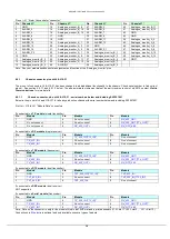
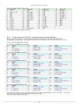
All of the module alarm outputs, both digital alarms and analogue monitors, are routed to a SCSI-3 connector on the rear panel of the
chassis. This connector also has the interface for the summary alarm relay if a module has been fitted to provide this function. This permits
the integration of the
ViaLiteHD
equipment into a Maintenance & Control system.
All of the module external power connections (LNA feeds) and chassis backplane external power connections are routed to a second SCSI-3
connector on the rear panel of the chassis.
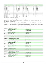
Module slots 1-14 have a data bus that can be used for sending and receiving data between modules.
4.3
Power Interface Management
External power can be provided to, or taken from the chassis
via the “Power Concentrator” connector J4, the current should be limited to 1A
per pin for single pins or 0.8A per pin for shared pins. The power level (sum of chassis and external power) must be within the capability of
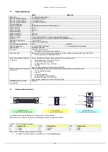
the chassis power supplies, see specification in section 5.2.
4.3.1
External backplane power
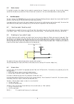
If the chassis is powered externally the input DC voltage measured at the power concentrator connector should be 12Vdc +/- 0.5V. If chassis
power supplies are also fitted we would advise that a low voltage drop diode (i.e. Schottky or similar) be used to OR the power feeds.
It is also possible to provide external power to a chassis fitted with PSUs, for this
reason the current share bus (CSB) is available on “Power
Concentrator” connector J4. If this option is used the chassis must be interfaced to
ViaLite Communications
approved external power
supplies, and the +12Vdc, GND and CSB lines for each power source should be connected in parallel.


