HRK3-HB-7
V
IA
L
ITE
HD
3U
CHASSIS
H
ANDBOOK
9
4.4.4
Module Alarm Defeat
In some installations, the chassis might not be fully populated with modules. In this case, the module alarm output for the vacant positions
would register a continuous alarm state and the Summary Alarm Output would also register an alarm condition.
It is very important to ensure that the DIP switches on the Summary alarm relay module or software alarm mask of the SNMP control module
for c
hassis positions where modules are “present” is set correctly. If a DIP switches/software mask is set incorrectly for a “present” module,
then if this module were to fail, NEITHER THE MODULE ALARM NOR THE SUMMARY ALARM WOULD DETECT THE FAILURE. The
front panel LEDs of the module will always register an alarm condition correctly regardless of the state of the DIP switches/software mask.
4.4.5
Using open collector alarms with controller cards
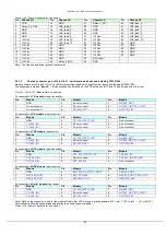
When a chassis is fitted with a controller card (i.e. SNMP and web controller or summary alarm card) all the alarm lines will be loaded and
pulled up. The alarm lines are pulled up to as shown below.
SNMP and web controller
pulled up to 3.3V via 4.7k ohms* (see warning below)
Summary Alarm
pulled up to 5V via 100k ohm, with series diode
*
Applying external voltage to these pins may cause damage, contact
ViaLite communications
Note: the alarm line for slot 14 is always pulled up irrespective of the card status, these cards are all fitted with summary alarm relays.
4.4.6
Using open collector alarms with RF switch and RF splitter cards
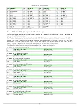
When a chassis is fitted with an RF switch or RF splitter card the alarm lines of the adjacent slots will be loaded and pulled up. The alarm
lines are pulled up to as shown below.
RF switch or RF splitter
pulled up to 5V via 10k ohm, with series diode
4.5
Heat management
The chassis is designed to meet its environmental specification, when operating in a typical configuration. A typical configuration is all
modules populated (13*Transceiver, 1*SNMP, 2*PSU), chassis power consumption 67 watts, no external DC power input or DC output and
no obstruction to convection air path.
Under normal operating conditions module slots 1-14 are cooled by convection, module slots 15 and 16 are force air cooled with exhaust at
rear of the chassis. The chassis will continue to run without the forced cooling provided by the integrated fan but its operating temperature
will be reduced.
Single PSU only fitted:
maximum operating temperature reduced by -5
C
Airflow above chassis blocked:
maximum operating temperature reduced by -10
C
Airflow below chassis blocked:
maximum operating temperature reduced by -5
C
No forced air:
maximum operating temperature reduced by -10
C
Also see section 5.2 that details the typical power consumption of most common types of modules.
4.6
Unused module positions
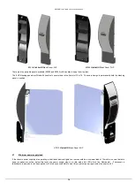
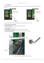
We advised that all unused slots be fitted with blanking panels. Different widths of blanking panel are available these fit the 5HP general
purpose (slots 1-13), 7HP controller card slots (slot 14), 6HP power supply slots (slots 15,16). They can be used with any
ViaLiteHD
19inch
chassis and will prevent accidental/unwanted access and the ingress of dust. Blanking panels available are.
85044
ViaLiteHD
Blank Panel, 5HP
Slots 1-13
85050
Reusable
ViaLiteHD
Blank Panel, 5HP Slots 1-13
HPS-0
ViaLiteHD
Blank Panel, 6HP
Slot 15, 16
85046
ViaLiteHD
Blank Panel, 7HP
Slot 14
85049
Reusable
ViaLiteHD
Blank Panel, 7HP Slot 14
Contact
ViaLite Communications
or your local agent for more details.
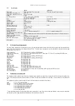
There are two types of the 5 and 7 HP blanking panels. The standard blanking panels are fitted with snap in plastic barbs. These are
designed to permanently hold the blanking panel in position. Please ensure that you have fully planned the configuration of your chassis, as
the plastic barbs are a close tolerance fit and removal results in the barbs being broken; the panel should then be discarded.


