29
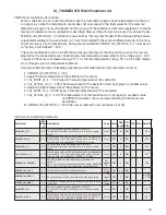
Equations:
FIELD_VAL = 100*(channel value - EU@0%) / (EU@100% - EU@0%) [XD_SCALE]
Direct: PV = channel value
Indirect: PV = (FIELD_VAL/100) * (EU@100% - EU@0%) + EU@0% [OUT_SCALE]
Ind Sqr Root: PV = sqrt(FIELD_VAL/100) * (EU@100% - EU@0%) + EU@0% [OUT_SCALE]
3.5 Supported Modes
O/S, Man and Auto.
3.6 To enable the Simulation mode
The hardware lock for the simulation mode is a reed switch mount-
ed in the PR5350 transmitter. The reed switch can be activated
with a special designed magnet which is mounted on the bus con-
nection terminals pin no. 1 and pin no. 2. Magnet type no. 8422 can
be ordered at PR electronics A/S.
3.7 Alarm Types
Standard block alarm plus standard HI_HI, HI, LO, and LO_LO alarms applied to OUT.
3.8 Mode Handling
Standard transition in and out of O/S.
Standard transition from Man to Auto and back.
3.9 Status Handling
The status values described in Output Parameter Formal Model of Part 1 apply, with the excep-
tion of the control sub-status values. The Uncertain - EU Range Violation status is always set
if the OUT value exceeds the OUT_SCALE range, and no worse condition exists. The following
options from STATUS_OPTS apply, where Limited refers to the sensor limits:
Propagate Fault Forward
Uncertain if Limited
BAD if Limited
Uncertain if Man mode
3.10 Initialisation
The PV filter must be initialised, but other than that, no special initialisation is required. This is
a pure calculation algorithm.
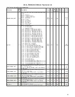
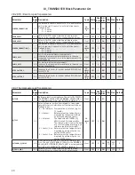
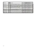
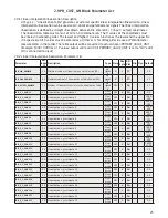
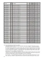
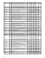
3.11 Analogue Input Blocks Parameter List, Fieldbus Foundation
Parameter
Rel.
Index Description
Type Store Size
byte
RO /
R/W Min Max Default
ST_REV
1
The revision level of the static data associated with the function
block. To support tracking changes in static parameter attributes,
the associated block’s static revision parameter will be incre-
mented each time a static parameter attribute value is changed.
Also, the associated block’s static revision parameter may be
incremented if a static parameter attribute is written but the
value is not changed.
Un-
signed
16
SRC
2
RO
0
TAG_DESC
2
The user description of the intended application of the block.
Octet
String
SRC
32
R/W
Spaces
STRATEGY
3
The strategy field can be used to identify grouping of blocks..
This data is not checked or processed by the block.
Un-
signed
16
SRC
2
R/W
0
ALERT_KEY
4
The identification number of the plant unit. This information
may be used in the host for sorting alarms, etc.
Un-
signed
8
SRC
1
R/W
1
255
0
MODE_BLK
5
The actual, target, permitted, and normal modes of the block.
DS-69
Mix
4
*
1, 1, 25,
16
BLOCK_ERR
6
This parameter reflects the error status associated with the
hardware or software components associated with a block. It is a
bit string, so that multiple errors may be shown.
Bit
String
D
2
RO
PV
7
Either the primary analog value for use in executing the func-
tion, or a process value associated with it. May also be calculat-
ed from the READBACK value of an AO block.
DS-65
D
5
RO


