30
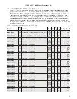
Parameter
Rel.
Index Description
Type Store Size
byte
RO /
R/W Min Max Default
OUT
8
The primary analog value calculated as a result of executing the
function.
DS-65
N
5
R/W
SIMULATE
9
Allows the transducer analog input or output to the block to be
manually supplied when simulate is enabled. When simulation
is disabled, the simulate value and status track the actual value
and status.
DS-82
D
11
R/W
Disable
XD_SCALE
10
The high and low scale values, engineering units code, and
number of digits to the right of the decimal point used with the
value obtained from the transducer for a specified channel.
DS-68
SRC
11
R/W
0-100%
OUT_SCALE
11
The high and low scale values, engineering units code, and
number of digits to the right of the decimal point to be used in
displaying the OUT parameter and parameters which have the
same scaling as OUT.
DS-68
SRC
11
R/W
0-100%
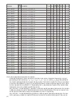
GRANT_DENY
12
Options for controlling access of host computer and local control
panels to operating, tuning and alarm parameters of the block.
DS-70
SRC
2
R/W
IO_OPTS
13
Options which the user may select to alter input and output
block processing.
Bit
String
SRC
2
R/W
0
STATUS_OPTS
14
Options which the user may select in the block processing of
status.
Bit
String
SRC
2
R/W
0
CHANNEL
15
The number of the logical hardware channel that is connected
to this I/O block. This information defines the transducer to be
used going to or from the physical world.
Un-
signed
16
SRC
2
R/W
1 or 2
L_TYPE
16
Determines if the values passed by the transducer block to the
AI block may be used directly (Direct) or if the value is in
different units and must be converted linearly (Indirect), or with
square root (Ind Sqr Root), using the input range defined by
the transducer and the associated output range.
Un-
signed
8
SRC
1
R/W
0
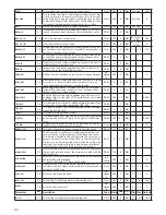
LOW_CUT
17
Limit used in square root processing. A value of zero percent of
scale is used in block processing if the transducer value falls
below this limit, in % of scale. This feature may be used to elim-
inate noise near zero for a flow sensor.
Float
SRC
4
R/W
0
PV_FTIME
18
Time constant of a single exponential filter for the PV, in sec-
onds.
Float
SRC
4
R/W
0
FIELD_VAL
19
Raw value of the field device in percent of thePV range, with a
status reflecting the Transducer condition, before signal charac-
terization (L_TYPE) or filtering (PV_FTIME).
DS-65
D
5
RO
UPDATE_EVT
20
This alert is generated by any change to the static data.
DS-73
D
14
RO
BLOCK_ALM
21
The block alarm is used for all configuration, hardware, connec-
tion failure or system problems in the block. The cause of the
alert is entered in the subcode field. The first alert to become
active will set the Active status in the Status attribute. As soon
as
the Unreported status is cleared by the alert reporting task,
another block alert may be reported without clearing the Active
status, if the subcode has changed.
DS-72
D
13
R/W
ALARM_SUM
22
The current alert status, unacknowledged states, unreported
states, and disabled states of the alarms associated with the
function block.
DS-74
Mix
8
R/W
ACK_OPTION
23
Selection of whether alarms associated with the block will be
automatically acknowledged.
Bit
String
SRC
2
R/W
0
ALARM_HYS
24
Amount the PV must return within the alarm limits before the
alarm condition clears. Alarm Hysteresis is expressed as a per-
cent of the PV span .
Float
SRC
4
R/W
0% 50%
0.5%
HI_HI_PRI
25
Priority of the high high alarm.
Un-
signed
8
SRC
1
R/W
0
15
0
HI_HI_LIM
26
The setting for high high alarm in engineering units.
Float
SRC
4
R/W
+INF
HI_PRI
27
Priority of the high alarm.
Un-
signed
8
SRC
1
R/W
0
15
0
HI_LIM
28
The setting for high alarm in engineering units.
Float
SRC
4
R/W
+INF
LO_PRI
29
Priority of the low alarm.
Un-
signed
8
SRC
1
R/W
0
15
0
LO_LIM
30
The setting for the low alarm in engineering units.
Float
SRC
4
R/W
-INF
LO_LO_PRI
31
Priority of the low low alarm.
Un-
signed
8
SRC
1
R/W
0
15
0
LO_LO_LIM
32
The setting of the low low alarm in engineering units.
Float
SRC
4
R/W
-INF
HI_HI_ALM
33
The status for high high alarm and its associated time stamp.
DS-71
D
16
R/W
HI_ALM
34
The status for high alarm and its associated time stamp.
DS-71
D
16
R/W
LO_ALM
35
The status of the low alarm and its associated time stamp.
DS-71
D
16
R/W
LO_LO_ALM
36
The status of the low low alarm and its associated time stamp.
DS-71
D
16
R/W


