background image

20 

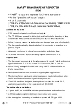
9106 - Product Version 9106-001

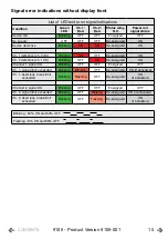
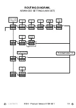
SCROLLING HELP TEXTS IN DISPLAY LINE 3

[01] 

[02] 

[03] 

[04] 

[05] 

[06] 


[09] 

[10] 

[11] 

[12] 


[15] 

[16] 

[17]

Set correct password [ PASS ] 

Enter advanced setup [ ADV.SET ] 

Set low limit for loop error detection [ LO.LIM1 ] [LO.LIM2 ] 

Set high limit for loop error detection [ HI.LIM1 ] [HI.LIM2 ] 

Enable rail status signal output? [ RAIL.ER ] 

Enter display setup [ SETUP ] 

Enter password setup [ SETUP ] 

Enter language setup [ SETUP ] 

Enter rail setup [ SETUP ] 

Adjust LCD contrast [ CONTRA ] 

Adjust LCD backlight [ LIGHT ] 

Write a 5-character tag no. [ ’TAGON ] [ ”TAGON ]  

Show loop values in display 

Show tag no. in display 

Alternate shown information in display 

Enable password protection [ EN.PASS ] 

Set new password [ NEW.PAS ] 

Select language [ LANGUA ]

CONTENTS

Summary of Contents for 9106

Page 1: ...P E N D I N G 9 1 0 6 S I G N A L S T H E B E S T P E N D I N G P E N D I N G H A R T T r a n s p a r e n t R e p e a t e r N o 9 1 0 6 V 1 0 0 U K P r o d u c t v e r s i o n 9 1 0 6 0 0 1 ...

Page 2: ... electronics A S offre une large gamme de produits pour le traite ment des signaux analogiques et numériques dans tous les domaines industriels La gamme de produits s étend des transmetteurs de température aux afficheurs des isolateurs aux interfaces SI jusqu aux modules universels Vous pouvez compter sur nos produits même dans les conditions d utilisation sévères p ex bruit électrique vibrations ...

Page 3: ... 7 PR 4501 display programming front 8 Order codes 9 Electrical specifications 9 Visualisation in 4501 of hardware software error 12 Connections 13 Block diagram 14 Signal error indications without display front 15 Configuration operating the function keys 16 Routing diagram 18 Routing diagram Advanced settings ADV SET 19 Scrolling help texts in display line 3 20 Appendix 21 IECEx Installation Dra...

Page 4: ...tages have been defined as the ranges 75 1500 Volt DC and 50 1000 Volt AC Technicians are qualified persons educated or trained to mount operate and also troubleshoot technically correct and in accordance with safety regulations Operators being familiar with the contents of this manual adjust and operate the knobs or potentiometers during normal operation WARNING The following operations should on...

Page 5: ...correct handling of the device please contact your local distributor or alternatively PR electronics A S www prelectronics com The use of stranded wires is not permitted for mains wiring except when wires are fitted with cable ends Descriptions of input output and supply connections are shown in the block diagram and on the side label The device is provided with field wiring terminals and shall be...

Page 6: ...ice is easily accessible CLEANING When disconnected the device may be cleaned with a cloth moistened with distilled water LIABILITY To the extent that the instructions in this manual are not strictly observed the customer cannot advance a demand against PR electronics A S that would otherwise exist according to the concluded sales agreement HOW TO DEMOUNT SYSTEM 9000 Picture 1 By lifting the botto...

Page 7: ...cation of the acceptable EMC performance level refer to the electrical specifications for the device The Low Voltage Directive 2006 95 EC and later amendments EN 61010 1 2001 The ATEX Directive 94 9 EC and later amendments EN 61241 0 2006 EN 61241 11 2006 EN 60079 0 2006 EN 60079 11 2007 EN 60079 15 2005 EN 60079 26 2007 ATEX certificate DEKRA 11ATEX0244 X Notified body DEKRA Certification B V 034...

Page 8: ...nication and stored data In a combination of 2 devices the safety system can reach a SIL 3 Application The device can be mounted in the safe area and in zone 2 div 2 and receive signals from zone 0 1 2 20 21 and 22 Class I II III Div 1 Gr A G Power supply and signal isolator with 2 way HART communication for 2 wire transmitters Dual channel versions can be used for signal splitter applications Mon...

Page 9: ... 20 21 22 Cl I II III Div 1 gr A G Zone 2 Cl 1 Div 2 gr A D or safe area Device status Device status Gnd Supply 19 2 31 2 VDC N C No connection No connection Power connection Channel 2 Output signals Analogue 4 20 mA Input signals Channel 1 2 wire transmitter Current 2 wire transmitter 2 wire transmitter Channel 2 Channel 1 Current 2 wire transmitter Same power rail as above CONTENTS ...

Page 10: ...tions interface for modification of operational parameters in 9106 When mounted in the process the display shows process values and device status Technical characteristics LCD display with 4 lines Line 1 H 5 57 mm shows status for each channel OK or error Line 2 H 3 33 mm shows loop current in mA for channel 1 or tag no line 3 H 3 33 mm shows loop current in mA for channel 2 or tag no and line 4 s...

Page 11: ...e 20 60 C Storage temperature 20 85 C Common specifications Supply voltage DC 19 2 31 2 VDC Max consumption 2 channels 3 W Fuse 1 25 A SB 250 VAC Isolation Input to any 300 VAC double reinforced isolation Analogue output to supply 300 VAC double reinforced isolation Status relay to supply 150 VAC double reinforced or 300 VAC basic isolation Communications interface Programming front 4501 HART comm...

Page 12: ... mm Protection degree IP20 Weight 250 g 265 g with 4501 DIN rail type DIN 46277 Current input Measurement range 3 5 23 mA Sensor error detection Loop break 4 20 mA 1 mA Input voltage drop Supplied unit 4 5 V Non supplied unit 6 V Current output Signal range span 3 5 23 mA Load max 20 mA 600 Ω 12 VDC Load stability 0 01 of span 100 Ω Current limit 28 mA General values Input type Absolute accuracy T...

Page 13: ...atus relay in safe area Max voltage 125 VAC 110 VDC Max current 0 5 AAC 0 3 ADC Max AC power 62 5 VA 32 W Marine approval Det Norske Veritas Ships Offshore Pending GOST R approval VNIIFTRI Cert No See www prelectronics com SIL certification exida Cert No Pending Observed authority requirements Standard EMC 2004 108 EC EN 61326 1 LVD 2006 95 EC EN 61010 1 ATEX 94 9 EC EN 60079 0 11 15 26 and EN 612...

Page 14: ...ror Hardware error RA ER RAM error Hardware error FL ERI Flash error Hardware error IN ER Initialisation error Hardware error C1 ER Hardware error channel 1 Hardware error C2 ER Hardware error channel 2 Hardware error DE ER General error All error indications in the display flash once per second The help text explains the error In case of cable fault the backlight also flashes This can be reset by...

Page 15: ... 42 52 43 53 44 54 COMMUNICATION FOUNDATION 12 14 11 13 12 14 11 13 250 Ω Tx 250 Ω COMMUNICATION FOUNDATION Supply Outputs Inputs Active Input Passive Input DCS PLC DCS PLC Current Active output Passive output Input Output 2 wire transmitter 24 VAC 24 VDC Connections are identical for channel 1 and channel 2 Input Output CONTENTS ...

Page 16: ...4 20 mA I mA mA I mA mA Tx 14 9106 Product Version 9106 001 BLOCK DIAGRAM Gnd Status relay N C Status relay N C Supply Power Rail connections Supply 24 VDC 2 wire transmitter 2 wire transmitter Channel 1 Channel 2 2 wire supply 2 wire supply Supply Green Ch 1 status Red Ch 2 status Red Gnd Gnd CONTENTS ...

Page 17: ...F De energized ON Ch 2 defective ch 1 OK Blinking OFF ON De energized ON Channel 1 signal OK Blinking OFF OFF Energized OFF Ch 1 signal limit exceeded Blinking Blinking OFF De energized ON if activated Ch 1 fixed loop break limit exceeded Blinking Flashing OFF De energized ON if activated Channel 2 signal OK Blinking OFF OFF Energized OFF Ch 2 signal limit exceeded Blinking OFF Blinking De energiz...

Page 18: ... or parameters If no key is activated for 1 minute the display will return to the default state 1 0 without saving the changed values or parameters Further explanations Password protection Programming access can be blocked by assigning a password The password is saved in the device in order to ensure a high degree of protection against unauthorised modifications to the configuration Default passwo...

Page 19: ...ht Setup of tag numbers with 5 alphanumerics Selection of functional readout in line 2 and 3 on the display choose between readout of loop current or tag no When selecting ALT the readout toggles between loop current and tag no Password Here you can choose a password between 0000 and 9999 in order to protect the unit against unauthorised modifications to the configuration The unit is delivered def...

Page 20: ...shown for 5 sec followed by txt 19 Line 3 shows the same as line 2 only for channel 2 Line 4 shows status for relay and communication 1 1 Only if password protected 1 2 Loop current limits identical for both channels can be deactivated by selecting values outside the range 3 5 23 mA Line 1 symbols OK Flashing error Continued on the page Routing diagram ADV SET ROUTING DIAGRAM If no key is activate...

Page 21: ...UT 1 2 LANG SETUP Txt 6 3 UK LANGUA Txt 17 3 DE DK ES FR IT SE UK 1 2 PASS SETUP Txt 6 3 3 YES EN PASS Txt 15 3 YES NO 1 2 NO 0000 NEW PAS Txt 16 3 9999 0000 1 2 RAIL SETUP Txt 6 3 YES RAIL ER Txt 5 3 YES NO 1 2 3 LOOP DISP Txt 12 3 ALT TAG STAT 1 2 9106 Product Version 9106 001 19 ROUTING DIAGRAM ADVANCED SETTINGS ADV SET To default state 1 0 CONTENTS ...

Page 22: ...ror detection HI LIM1 HI LIM2 Enable rail status signal output RAIL ER Enter display setup SETUP Enter password setup SETUP Enter language setup SETUP Enter rail setup SETUP Adjust LCD contrast CONTRA Adjust LCD backlight LIGHT Write a 5 character tag no TAGON TAGON Show loop values in display Show tag no in display Alternate shown information in display Enable password protection EN PASS Set new ...

Page 23: ...9106 Product Version 9106 001 21 APPENDIX IECEx Installation drawing ATEX Installation drawing FM Installation drawing CONTENTS ...

Page 24: ...1 2011 IEC60079 0 2011 IEC60079 26 2006 Supply terminal 31 32 Voltage 19 2 31 2 VDC Status Relay terminal 33 34 Zone 2 installation Voltage max 125 VAC 110 VDC 32 VAC 32 VDC Power max 62 5 VA 32 W 32 VAC 32 VDC Current max 0 5 A AC 0 3 ADC 0 5 A AC 1 ADC Installation notes Install in pollution degree 2 overvoltage category II as defined in IEC 60664 1 Do not separate connectors when energized and ...

Page 25: ... Uo 28 V Io 93 mA Po 0 65 W IIC IIB IIA I Co 0 08µF 0 600µF 2 15 µF 3 76 µF Lo 3 mH 12 mH 25 mH 30 mH 20 Ta 60ºC terminal 11 12 13 14 terminal 31 32 33 34 terminal 91 92 93 94 95 Um 253 V max 400 Hz 44 43 42 41 54 53 52 51 34 33 32 31 14 13 12 11 9106 4501 91 92 93 94 95 Power Rail CH1 CH2 T T _ _ 9106B2A 9106B2B Ex input Loop current source CH1 terminal 43 44 CH2 terminal 53 54 Uo 25 6 V Io 100 m...

Page 26: ... 20 21 22 or Zone 2 9106B1A 9106B1B 9106B2A 9106B2B Ex input External current source CH1 terminal 41 42 CH2 terminal 51 52 Uo 0 V Io 0 mA Po 0 mW Ui 30 V Ii 120 mA Pi 0 85 mA Ci 2 nF Li 0 μH 44 43 42 41 54 53 52 51 34 33 32 31 14 13 12 11 9106 4501 91 92 93 94 95 Power Rail CH1 CH2 _ _ 20 Ta 60ºC terminal 11 12 13 14 terminal 31 32 33 34 terminal 91 92 93 94 95 Um 253 V max 400 Hz CONTENTS ...

Page 27: ...minal 52 Uo 28 V Io 93 mA Po 0 65 W IIC IIB IIA I Co 0 08µF 0 600µF 2 15 µF 3 76 µF Lo 3 mH 12 mH 25 mH 30 mH 20 Ta 60ºC terminal 11 12 13 14 terminal 31 32 33 34 terminal 91 92 93 94 95 Um 253 V max 400 Hz 44 43 42 41 54 53 52 51 34 33 32 31 14 13 12 11 9106 4501 91 92 93 94 95 Power Rail CH1 CH2 T 9106B2A 9106B2B Ex input Loop current source 1 to 2 CH1 terminal 44 CH2 terminal 52 Uo 25 6 V Io 10...

Page 28: ... 2 20 21 22 or Zone 2 terminal 11 12 13 14 terminal 31 32 33 34 terminal 91 92 93 94 95 Um 253 V max 400 Hz 9106B1A 9106B1B 9106B2A 9106B2B Ex input External current source 1 to 2 CH1 terminal 42 CH2 terminal 51 Uo 0 V Io 0 mA Po 0 W Ui 30 V Ii 120 mA Pi 0 85 W Ci 4 nF Li 0 μH 20 Ta 60ºC 44 43 42 41 54 53 52 51 34 33 32 31 14 13 12 11 9106 4501 91 92 93 94 95 Power Rail CH1 CH2 CONTENTS ...

Page 29: ...79 26 2007 EN 61241 11 2006 Supply terminal 31 32 Voltage 19 2 31 2 VDC Status Relay terminal 33 34 Zone 2 installation Voltage max 125 VAC 110 VDC 32 VAC 32 VDC Power max 62 5 VA 32 W 32 VAC 32 VDC Current max 0 5 A AC 0 3 ADC 0 5 A AC 1 ADC Installation notes Install in pollution degree 2 overvoltage category II as defined in EN 60664 1 Do not separate connectors when energized and an explosive ...

Page 30: ...53 54 Uo 28 V Io 93 mA Po 0 65 W IIC IIB IIA I Co 0 08µF 0 600µF 2 15 µF 3 76 µF Lo 3 mH 12 mH 25 mH 30 mH 20 Ta 60ºC terminal 11 12 13 14 terminal 31 32 33 34 terminal 91 92 93 94 95 Um 253 V max 400 Hz 44 43 42 41 54 53 52 51 34 33 32 31 14 13 12 11 9106 4501 91 92 93 94 95 Power Rail CH1 CH2 T T _ _ 9106B2A 9106B2B Ex input Loop current source CH1 terminal 43 44 CH2 terminal 53 54 Uo 25 6 V Io ...

Page 31: ... 1 2 20 21 22 or Zone 2 9106B1A 9106B1B 9106B2A 9106B2B Ex input External current source CH1 terminal 41 42 CH2 terminal 51 52 Uo 0 V Io 0 mA Po 0 mW Ui 30 V Ii 120 mA Pi 0 85 mA Ci 2 nF Li 0 μH 44 43 42 41 54 53 52 51 34 33 32 31 14 13 12 11 9106 4501 91 92 93 94 95 Power Rail CH1 CH2 _ _ 20 Ta 60ºC terminal 11 12 13 14 terminal 31 32 33 34 terminal 91 92 93 94 95 Um 253 V max 400 Hz ...

Page 32: ...minal 52 Uo 28 V Io 93 mA Po 0 65 W IIC IIB IIA I Co 0 08µF 0 600µF 2 15 µF 3 76 µF Lo 3 mH 12 mH 25 mH 30 mH 20 Ta 60ºC terminal 11 12 13 14 terminal 31 32 33 34 terminal 91 92 93 94 95 Um 253 V max 400 Hz 44 43 42 41 54 53 52 51 34 33 32 31 14 13 12 11 9106 4501 91 92 93 94 95 Power Rail CH1 CH2 T 9106B2A 9106B2B Ex input Loop current source 1 to 2 CH1 terminal 44 CH2 terminal 52 Uo 25 6 V Io 10...

Page 33: ...e 0 1 2 20 21 22 or Zone 2 terminal 11 12 13 14 terminal 31 32 33 34 terminal 91 92 93 94 95 Um 253 V max 400 Hz 9106B1A 9106B1B 9106B2A 9106B2B Ex input External current source 1 to 2 CH1 terminal 42 CH2 terminal 51 Uo 0 V Io 0 mA Po 0 W Ui 30 V Ii 120 mA Pi 0 85 W Ci 4 nF Li 0 μH 20 Ta 60ºC 44 43 42 41 54 53 52 51 34 33 32 31 14 13 12 11 9106 4501 91 92 93 94 95 Power Rail CH1 CH2 ...

Page 34: ...nal 33 34 Zone 2 installation Voltage max 125 VAC 110 VDC 32 VAC 32 VDC Power max 62 5 VA 32 W 32 VAC 32 VDC Current max 0 5 A AC 0 3 ADC 0 5 A AC 1 ADC Installation notes In Class I Division 2 installations the subject equipment shall be mounted within a tool secured enclosure which is capable of accepting one or more of the Class I Division 2 wiring methods specified in the National Electrical C...

Page 35: ...3 52 51 34 33 32 31 14 13 12 11 9106 4501 91 92 93 94 95 Power Rail CH1 CH2 T T _ _ 9106B2A 9106B2B Ex input Loop current source CH1 terminal 43 44 CH2 terminal 53 54 Uo 25 6 V Io 100 mA Po 0 64 W IIC or A B IIB or C E F IIA or D G Co 0 10µF 0 800µF 2 75 µF Lo 2 mH 9 mH 15 mH Simple Apparatus or Intrinsic safe apparatus with entity parameters Vmax Ui Vt Uo Imax Ii It Io Pi Pt Po Ca Ccable Ci La Lc...

Page 36: ... 51 34 33 32 31 14 13 12 11 9106 4501 91 92 93 94 95 Power Rail CH1 CH2 _ _ 20 Ta 60ºC terminal 11 12 13 14 terminal 31 32 33 34 terminal 91 92 93 94 95 Um 253 V max 400 Hz Simple Apparatus or Intrinsic safe apparatus with entity parameters Vmax Ui Vt Uo Imax Ii It Io Pi Pt Po Ca Ccable Ci La Lcable Li Hazardous Classified Location Unclassified Location or Class I II III Division 1 Group A B C D E...

Page 37: ...15 µF Lo 3 mH 12 mH 25 mH 20 Ta 60ºC terminal 11 12 13 14 terminal 31 32 33 34 terminal 91 92 93 94 95 Um 253 V max 400 Hz 44 43 42 41 54 53 52 51 34 33 32 31 14 13 12 11 9106 4501 91 92 93 94 95 Power Rail CH1 CH2 T 9106B2A 9106B2B Ex input Loop current source 1 to 2 CH1 terminal 44 CH2 terminal 52 Uo 25 6 V Io 100 mA Po 0 64 W IIC or A B IIB or C E F IIA or D G Co 0 10µF 0 800µF 2 75 µF Lo 2 mH ...

Page 38: ...1 Uo 0 V Io 0 mA Po 0 W Ui 30 V Ii 120 mA Pi 0 85 W Ci 4 nF Li 0 μH 20 Ta 60ºC 44 43 42 41 54 53 52 51 34 33 32 31 14 13 12 11 9106 4501 91 92 93 94 95 Power Rail CH1 CH2 Simple Apparatus or Intrinsic safe apparatus with entity parameters Vmax Ui Vt Uo Imax Ii It Io Pi Pt Po Ca Ccable Ci La Lcable Li Hazardous Classified Location Unclassified Location or Class I II III Division 1 Group A B C D E F...

Page 39: ... Galvanic isolators for analogue and digital signals as well as HART signals A wide product range with both loop powered and universal isolators featuring linearisation inversion and scaling of output signals Isolation Interfaces for analogue and digital signals aswellasHART signalsbetweensensors I Pconverters frequency signals and control systems in Ex zone 0 1 2 and for some modules in zone 20 2...

Page 40: ...ax 45 86 37 30 85 www prelectronics fr sales prelectronics fr www prelectronics de sales prelectronics de www prelectronics es sales prelectronics es www prelectronics it sales prelectronics it www prelectronics se sales prelectronics se www prelectronics co uk sales prelectronics co uk www prelectronics com sales prelectronics com ...

Reviews: