background image


6334V105 

43

Vergleichstellenkompensation (CJC) ..........   < ±1,0°C
Fühlerfehlererkennung ................................   Ja
Fühlerfehlerstrom:
 

Bei Erkennung ......................................   Nom. 33 mA


Sonst ....................................................   0 mA

Spannungseingänge:

Messbereich ...............................................   -12...150 mV
Min. Messbereich (Spanne) ........................   5 mV
Eingangswiederstand .................................   10 M

Ω

Ausgänge:
Stromausgänge:

Signalbereich ..............................................   4...20 mA
Min. Signalbereich ......................................   16 mA
Aktualisierungszeit......................................   440 ms
Ausgangssignal bei EEpromfehler .............  

 3,5 mA

Belastungswiederstand ..............................  

 (U

Versorg.

 - 7,2) / 0,023 [

Ω

]

Belastungsstabilität ..........................................  < ±0,01% d. Messsp. / 100 

Ω

Sensorfehlanzeige:

Programmierbar..........................................   3,5...23 mA
NAMUR NE43 aufsteuernd ........................   23 mA
NAMUR NE43 zusteuernd..........................   3,5 mA

d. Messspanne = der gewählten Messspanne

Summary of Contents for PRetrans 6334

Page 1: ...K UK FR DE Side 1 Page 13 Page 25 Seite 37 S I G N A L S T H E B E S T 6 3 3 4 2 W i r e P r o g r a m m a b l e T r a n s m i t t e r N o 6 3 3 4 V 1 0 5 I N 1 0 2 1 F r o m s e r n o 0 9 9 2 5 6 0 0 0 ...

Page 2: ...ctronics A S offre une large gamme de produits pour le traite ment des signaux analogiques et numériques dans tous les domaines industriels La gamme de produits s étend des transmetteurs de température aux afficheurs des isolateurs aux interfaces SI jusqu aux modules universels Vous pouvez compter sur nos produits même dans les conditions d utilisation sévères p ex bruit électrique vibrations et f...

Page 3: ...eserklæring 2 Anvendelse 3 Teknisk karakteristik 3 Montage installation 3 Applikationer 4 Bestillingsskema 6334 5 Elektriske specifikationer 5 Tilslutninger 9 Blokdiagram 10 Programmering 11 Appendix 48 ATEX Installation Drawings UK FR DE DK 6334A 49 ATEX Installation Drawings UK FR DE DK 6334B 53 ...

Page 4: ...øjelser EN 61326 1 2006 For specifikation af det acceptable EMC niveau henvises til modulets elektriske specifikationer ATEX direktivet 94 9 EF og senere tilføjelser EN 60079 0 2006 EN 60079 11 2007 EN 60079 15 2005 og EN 60079 26 2007 ATEX certifikat KEMA 10ATEX0005 X 6334A ATEX certifikat KEMA 06ATEX0115 6334B Bemyndiget organ KEMA Quality B V 0344 Utrechtseweg 310 6812 AR Arnhem P O Box 5185 68...

Page 5: ...V signaler eventuelt lineariseret efter defineret lineariseringsfunktion til et 4 20 mA signal Teknisk karakteristik PR6334 kan af brugeren i løbet af få sekunder programmeres til at måle inden for alle normerede TC temperaturområder CJC kompensering med monteret CJC stik Udgangssignalet kan programmeres til en begrænsning Der er løbende sikkerhedscheck af gemte data Montage installation Monteres ...

Page 6: ...4 6334V105 V mA V mA TC til 4 20 mA 2 trådsinstallation i kontrolrum 2 trådsinstallation i kontrolrum mV til 4 20 mA Applikationer ...

Page 7: ... Ex 1500 VAC Opvarmningstid 5 min Kommunikationsinterface Loop Link Signal støjforhold min 60 dB Reaktionstid programmerbar 1 60 s EEprom fejlcheck 3 5 s Signaldynamik indgang 18 bit Signaldynamik udgang 16 bit Kalibreringstemperatur 20 28 C Nøjagtighed størst af generelle og basisværdier Bestillingsskema 6334 Type Version Galvanisk isolation Kanaler 6334 Standard A ATEX Ex B 1500 VAC 2 Enkelt A D...

Page 8: ... µV C TC type E J K L N T U 1 C 0 05 C C TC type B R S W3 W5 LR 2 C 0 2 C C EMC immunitetspåvirkning 0 5 af span Udvidet EMC immunitet NAMUR NE 21 A kriterium gniststøj 1 af span Type Min temperatur Max temperatur Min span Standard B E J K L N R S T U W3 W5 LR 400 C 100 C 100 C 180 C 100 C 180 C 50 C 50 C 200 C 200 C 0 C 0 C 200 C 1820 C 1000 C 1200 C 1372 C 900 C 1300 C 1760 C 1760 C 400 C 600 C ...

Page 9: ...de span 5 mV Indgangsmodstand 10 MΩ Udgange Strømudgange Signalområde 4 20 mA Min signalområde 16 mA Opdateringstid 440 ms Udgangssignal ved EEpromfejl 3 5 mA Belastningsmodstand Vforsyn 7 2 0 023 Ω Belastningsstabilitet 0 01 af span 100 Ω Følerfejlsdetektering Programmerbar 3 5 23 mA Namur NE43 Upscale 23 mA Namur NE43 Downscale 3 5 mA Af span Af det aktuelt valgte område ...

Page 10: ...6331QA02 Ex I S godkendelse 6334B KEMA 06ATEX0115 II 1 G Ex ia IIC T6 T5 Max omgivelsestemp for T5 60 C Max omgivelsestemp for T6 40 C ATEX må anvendes i zone 0 1 eller 2 ATEX Installation Drawing No 6331QA01 GOST R godkendelse VNIIM VNIIFTRI Cert no Se www prelectronics dk Overholdte myndighedskrav Standard EMC 2004 108 EF EN 61326 1 ATEX 94 9 EF EN 60079 0 EN 60079 11 EN 60079 15 EN 60079 26 ...

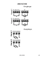
Page 11: ...mA mA 23 21 22 11 12 13 41 42 44 CJC 41 42 44 CJC 51 54 CJC 52 51 54 CJC 52 Kanal 1 Kanal 2 Indgange Kanal 1 Kanal 2 Udgange 2 Trådsinstallation 2 Trådsinstallation mV mV TC intern CJC TC intern CJC Tilslutninger ...

Page 12: ...4 13 23 11 21 43 42 41 53 54 51 52 m A M U X 4 m A 6 3 3 4 6 3 3 4 PGA D A A D C P U E E P R O M CH 1 CH 2 m V Forsyning 4 20 mA Forsyning TC mV Ex kredsløb kun 6334B Internt CJC stik er monteret ved levering Komm Blokdiagram ...

Page 13: ...s til stikbenene Loop Link må ikke benyttes til kommunikation med moduler installeret i Ex område Bestilling Loop Link PRetrans 6334 13 23 11 21 Loop Link 5909 USB 5905 RS232 File Product Input Output Communication Language Option 08 30 00 PRetop 5331 Date 2004 8 10 043201594 PRelectronics Analog input Analog output Serial no Input type Output type 4 20mA Upscale Sensor error Pt100 DIN IEC 0 00 50...

Page 14: ...12 6334V105 ...

Page 15: ...rmity 14 Application 15 Technical characteristics 15 Mounting installation 15 Applications 16 Order 6334 17 Electrical specifications 17 Connections 21 Block diagram 22 Programming 23 Appendix 48 ATEX Installation Drawings UK FR DE DK 6334A 49 ATEX Installation Drawings UK FR DE DK 6334B 53 ...

Page 16: ...ts EN 61326 1 2006 For specification of the acceptable EMC performance level refer to the electrical specifications for the module The ATEX Directive 94 9 EC and later amendments EN 60079 0 2006 EN 60079 11 2007 EN 60079 15 2005 and EN 60079 26 2007 ATEX certificate KEMA 10ATEX0005 X 6334A ATEX certificate KEMA 06ATEX0115 6334B Notified body KEMA Quality B V 0344 Utrechtseweg 310 6812 AR Arnhem P ...

Page 17: ... linearisation function Technical characteristics Within a few seconds the user can program PR6334 to measure temperatures within all TC ranges defined by the norms Cold junction compensation CJC with a mounted CJC connector A limit can be programmed on the output signal Continuous check of vital stored data for safety reasons Mounting installation Mounted vertically or horizontally on a DIN rail ...

Page 18: ...16 6334V105 V mA V mA 2 wire installation in control room 2 wire installation in control room TC to 4 20 mA mV to 4 20 mA Applications ...

Page 19: ...C ATEX Ex 1500 VAC Warm up time 5 min Communications interface Loop Link Signal noise ratio min 60 dB Response time programmable 1 60 s EEprom error check 3 5 s Signal dynamics input 18 bit Signal dynamics output 16 bit Calibration temperature 20 28 C Accuracy the greater of general and basic values Order 6334 Type Version Galvanic isolation Channels 6334 Standard A ATEX Ex B 1500 VAC 2 Single A D...

Page 20: ... K L N T U 1 C 0 05 C C TC type B R S W3 W5 LR 2 C 0 2 C C EMC immunity influence 0 5 of span Extended EMC immunity NAMUR NE 21 A criterion burst 1 of span Type Min temperature Max temperature Min span Standard B E J K L N R S T U W3 W5 LR 400 C 100 C 100 C 180 C 100 C 180 C 50 C 50 C 200 C 200 C 0 C 0 C 200 C 1820 C 1000 C 1200 C 1372 C 900 C 1300 C 1760 C 1760 C 400 C 600 C 2300 C 2300 C 800 C 1...

Page 21: ... Min span 5 mV Input resistance 10 MΩ Outputs Current outputs Signal range 4 20 mA Min signal range 16 mA Updating time 440 ms Output signal at EEprom error 3 5 mA Load resistance Vsupply 7 2 0 023 Ω Load stability 0 01 of span 100 Ω Sensor error detection Programmable 3 5 23 mA Namur NE43 Upscale 23 mA Namur NE43 Downscale 3 5 mA Of span Of the presently selected range ...

Page 22: ...x I S approval 6334B KEMA 06ATEX0115 II 1 G Ex ia IIC T6 T5 Max ambient temperature for T5 60 C Max ambient temperature for T6 40 C ATEX applicable in zone 0 1 or 2 ATEX Installation Drawing No 6331QA01 GOST R approval VNIIM VNIIFTRI Cert no See www prelectronics com Observed authority requirements Standard EMC 2004 108 EC EN 61326 1 ATEX 94 9 EC EN 60079 0 EN 60079 11 EN 60079 15 EN 60079 26 ...

Page 23: ...mA 23 21 22 11 12 13 41 42 44 CJC 41 42 44 CJC 51 54 CJC 52 51 54 CJC 52 Channel 1 Channel 2 Channel 2 Inputs Channel 1 Outputs 2 wire installation 2 wire installation mV mV TC internal CJC TC internal CJC Connections ...

Page 24: ...4 13 23 11 21 43 42 41 53 54 51 52 m A M U X 4 m A 6 3 3 4 6 3 3 4 PGA D A A D C P U E E P R O M CH 1 CH 2 m V Comm Supply 4 20 mA Ex circuit only 6334B TC mV At delivery internal CJC connector is mounted Supply Block diagram ...

Page 25: ...ins Loop link is not approved for communication with modules installed in harzard ous Ex areas Order Loop Link PRetrans 6334 13 23 11 21 Loop Link 5909 USB 5905 RS232 File Product Input Output Communication Language Option 08 30 00 PRetop 5331 Date 2004 8 10 043201594 PRelectronics Analog input Analog output Serial no Input type Output type 4 20mA Upscale Sensor error Pt100 DIN IEC 0 00 50 00 C 3 ...

Page 26: ...24 6334V105 ...

Page 27: ...ité CE 26 Application 27 Caractéristiques techniques 27 Montage installation 27 Applications 28 Référence 6334 29 Spécifications 29 Connexions 33 Schéma de principe 34 Programmation 35 Appendix 48 ATEX Installation Drawings UK FR DE DK 6334A 49 ATEX Installation Drawings UK FR DE DK 6334B 53 ...

Page 28: ...1 2006 Pour une spécification du niveau de rendement acceptable CEM EMC renvoyer aux spécifications électriques du module La directive ATEX 94 9 EC et les modifications subséquentes EN 60079 0 2006 EN 60079 11 2007 EN 60079 15 2005 et EN 60079 26 2007 Certificat ATEX KEMA 10ATEX0005 X 6334A Certificat ATEX KEMA 06ATEX0115 6334B Organisme notifié KEMA Quality B V 0344 Utrechtseweg 310 6812 AR Arnhe...

Page 29: ...entuellement linéarisé suivant une fonction de linéarisation Caractéristiques techniques Le PR6334 peut être programmé de manière simple et rapide La compensation de soudure froide CSF est réalisée à l aide d un capteur de température intégré au module Le signal de sortie peut être programmé avec un limite Montage installation Pour montage vertical ou horizontal sur rail DIN En version 2 voies 84 ...

Page 30: ...28 6334V105 V mA V mA Installation 2 fils en salle de contrôle Installation 2 fils en salle de contrôle TC en 4 20 mA mV en 4 20 mA Applications ...

Page 31: ...mps de chauffe 5 min Kit de programmation Loop Link Rapport signal bruit Min 60 dB Temps de réponse programmable 1 60 s Vérification de l EEprom 3 5 s Dynamique du signal d entrée 18 bit Dynamique du signal de sortie 16 bit Température d étalonnage 20 28 C Précision la plus grande des valeurs générales et de base Référence 6334 Type Version Isolation galvanique Voies 6334 Standard A ATEX Ex B 1500...

Page 32: ...t 10 µV 1 µV C Type TC E J K L N T U 1 C 0 05 C C Type TC B R S W3 W5 LR 2 C 0 2 C C Immunité CEM 0 5 de l EC Immunité CEM améliorée NAMUR NE 21 critère A burst 1 de l EC Type Température min Température max Plage min Standard B E J K L N R S T U W3 W5 LR 400 C 100 C 100 C 180 C 100 C 180 C 50 C 50 C 200 C 200 C 0 C 0 C 200 C 1820 C 1000 C 1200 C 1372 C 900 C 1300 C 1760 C 1760 C 400 C 600 C 2300 ...

Page 33: ...e min 5 mV Résistance d entrée 10 MΩ Sorties Sorties courant Gamme de mesure 4 20 mA Plage de mesure min 16 mA Temps de scrutation 440 ms Sortie en cas de corruption de l EEprom 3 5 mA Résistance de charge Valim 7 2 0 023 Ω Stabilité de charge 0 01 de l EC 100 Ω Détection de rupture de sonde Programmable 3 5 23 mA Namur NE43 Haut d échelle 23 mA Namur NE43 Bas d échelle 3 5 mA EC Echelle configuré...

Page 34: ...02 Approbation Ex S I 6334B KEMA 06ATEX0115 II 1 G Ex ia IIC T6 T5 Température ambiante max T5 60 C Température ambiante max T6 40 C ATEX applicable en zone 0 1 ou 2 ATEX Installation Drawing No 6331QA01 Approbation GOST R VNIIM VNIIFTRI Cert no Voir www prelectronics fr Agréments et homologations Standard CEM 2004 108 CE EN 61326 1 ATEX 94 9 CE EN 60079 0 EN 60079 11 EN 60079 15 EN 60079 26 ...

Page 35: ... 33 mA mA 23 21 22 11 12 13 41 42 44 CJC 41 42 44 CJC 51 54 CJC 52 51 54 CJC 52 Voie 1 Voie 2 Voie 2 Entrées Voie 1 Sorties Installation 2 fils Installation 2 fils mV mV TC CSF interne TC CSF interne Connexions ...

Page 36: ...2 41 53 54 51 52 m A M U X 4 m A 6 3 3 4 6 3 3 4 PGA D A A D C P U E E P R O M CH 1 CH 2 m V Comm Alimentation 4 20 mA Circuit S I seulement 6334B TC mV Le produit est livré avec le s bornier s CSF déjà monté s Alimentation Schema de principe ...

Page 37: ... programmation Loop Link ne doit pas être utilisé pour communication avec des modules installés en zone dangereuse Numéro de référence Loop Link PRetrans 6334 13 23 11 21 Loop Link 5909 USB 5905 RS232 File Product Input Output Communication Language Option 08 30 00 PRetop 5331 Date 2004 8 10 043201594 PRelectronics Analog input Analog output Serial no Input type Output type 4 20mA Upscale Sensor e...

Page 38: ...36 6334V105 ...

Page 39: ...serklärung 38 Verwendung 39 Technische Merkmale 39 Montage Installation 39 Anwendungen 40 Bestellangaben 6334 41 Elektrische Daten 41 Anschlüsse 45 Blockdiagramm 46 Programmierung 47 Appendix 48 ATEX Installation Drawings UK FR DE DK 6334A 49 ATEX Installation Drawings UK FR DE DK 6334B 53 ...

Page 40: ...ungen EN 61326 1 2006 Zur Spezifikation des zulässigen Erfüllungsgrades siehe die Elektrische Daten des Moduls Die ATEX Richtlinien 94 9 EC und nachfolgende Änderungen EN 60079 0 2006 EN 60079 11 2007 EN 60079 15 2005 und EN 60079 26 2007 ATEX Zertifikat KEMA 10ATEX0005 X 6334A ATEX Zertifikat KEMA 06ATEX0115 6334B Zulassungsstelle KEMA Quality B V 0344 Utrechtseweg 310 6812 AR Arnhem P O Box 5185...

Page 41: ...ert Technische Merkmale PR6334 kann vom Benutzer innerhalb von wenigen Sekunden zur Messung in allen genormten TE Temperaturbereiche programmiert werden CJC Vergleichsstellenkompsation mit montierten CJC Anschlusssteckern Das Ausgangssignal kann für eine Begrenzung programmiert werden Die gespeicherten Daten werden laufend kontrolliert Montage Installation Wird vertikal oder horizontal auf DIN Sch...

Page 42: ...40 6334V105 V mA V mA TE in 4 20 mA 2 Draht Installation im Kontrollraum 2 Draht Installation im Kontrollraum mV in 4 20 mA Anwendungen ...

Page 43: ...mzeit 5 Min Kommunikationsschnittstelle Loop Link Signal Rauschverhältnis Min 60 dB Ansprechzeit programmierbar 1 60 s EEprom Fehlerkontrolle 3 5 s Signaldynamik Eingang 18 Bit Signaldynamik Ausgang 16 Bit Kalibrierungstemperatur 20 28 C Genauigkeit höherer Wert von allgemeinen und Grundwerten Bestellangaben 6334 Typ Version Galvanische Trennung Kanäle 6334 Standard A ATEX Ex B 1500 VAC 2 Einfach ...

Page 44: ... µV 1 µV C TE Typ E J K L N T U 1 C 0 05 C C TE Typ B R S W3 W5 LR 2 C 0 2 C C EMV Immunitätswirkung 0 5 d Messsp Erweiterte EMV Immunität NAMUR NE 21 A Kriterium Burst 1 d Messsp Typ Min Temperatur Max Temperatur Min Spanne Norm B E J K L N R S T U W3 W5 LR 400 C 100 C 100 C 180 C 100 C 180 C 50 C 50 C 200 C 200 C 0 C 0 C 200 C 1820 C 1000 C 1200 C 1372 C 900 C 1300 C 1760 C 1760 C 400 C 600 C 23...

Page 45: ...ne 5 mV Eingangswiederstand 10 MΩ Ausgänge Stromausgänge Signalbereich 4 20 mA Min Signalbereich 16 mA Aktualisierungszeit 440 ms Ausgangssignal bei EEpromfehler 3 5 mA Belastungswiederstand UVersorg 7 2 0 023 Ω Belastungsstabilität 0 01 d Messsp 100 Ω Sensorfehlanzeige Programmierbar 3 5 23 mA Namur NE43 aufsteuernd 23 mA Namur NE43 zusteuernd 3 5 mA d Messspanne der gewählten Messspanne ...

Page 46: ...o 6331QA02 Ex I S Zulassung 6334B KEMA 06ATEX0115 II 1 G Ex ia IIC T6 T5 Max Umgebungstemp für T5 60 C Max Umgebungstemp für T6 40 C ATEX für Anwendung in Zone 0 1 ou 2 ATEX Installation Drawing No 6331QA01 GOST R Zulassung VNIIM VNIIFTRI Cert no Siehe www prelectronics de Eingehaltene Richtlinien Norm EMV 2004 108 EG EN 61326 1 ATEX 94 9 EG EN 60079 0 EN 60079 11 EN 60079 15 EN 60079 26 ...

Page 47: ... 21 22 11 12 13 41 42 44 CJC 41 42 44 CJC 51 54 CJC 52 51 54 CJC 52 Eingänge Kanal 1 Kanal 2 Kanal 1 Kanal 2 Ausgänge 2 Draht Installation 2 Draht Installation mV mV TE interne CJC TE interne CJC Kanal 1 Kanal 2 Anschlüsse ...

Page 48: ...43 42 41 53 54 51 52 m A M U X 4 m A 6 3 3 4 6 3 3 4 PGA D A A D C P U E E P R O M CH 1 CH 2 m V Komm Versorgung 4 20 mA Ex Kreislauf nur 6334B TE mV Der interne CJC Anschlussstecker ist bei der Lieferung montiert Versorgung Blockdiagramm ...

Page 49: ...n Loop Link darf nicht zur kommunikation mit Modulen die in Ex gefährdeten Bereichen installiert sind benutz werden Bestellangabe Loop Link PRetrans 6334 13 23 11 21 Loop Link 5909 USB 5905 RS232 File Product Input Output Communication Language Option 08 30 00 PRetop 5331 Date 2004 8 10 043201594 PRelectronics Analog input Analog output Serial no Input type Output type 4 20mA Upscale Sensor error ...

Page 50: ...48 6334V105 Appendix ATEX Installation Drawings 6334A UK FR DE DK ATEX Installation Drawings 6334B UK FR DE DK ...

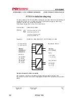
Page 51: ...ards EN 60079 0 2006 EN 60079 11 2007 EN 60079 15 2005 Special conditions for safe use For use in a potentially explosive atmosphere of flammable gasses vapours or mists the transmitter shall be mounted in an enclosure providing a degree of protection of at least IP54 in accordance to EN60529 II 3 G Ex nA nL IIC T6 T5 II 3 G Ex nL IIC T6 T5 II 3 G Ex nA ic IIC T6 T5 II 3 G Ex ic IIC T6 T5 Hazardou...

Page 52: ...uage Standards EN 60079 0 2006 EN 60079 11 2007 EN 60079 15 2005 Conditions spécifiques à l utilisation sûre Pour utilisation dans les atmosphères potentiellement explosibles dû à la présence de gaz vapeurs ou brumes inflammables le transmetteur doit être installé dans un boîtier de protection assurant un degré d étanchéité d au moins IP54 conformément à l EN 60529 II 3 G Ex nA nL IIC T6 T5 II 3 G...

Page 53: ... Markierung Richtlinien EN 60079 0 2006 EN 60079 11 2007 EN 60079 15 2005 Sonderbedingungen für sichere Anwendung Für Anwendung in einer potentiellen explosiven Atmosphäre basierend auf entflammbaren Gas Dämpfen Nebeln muss der Messumformer in einem Gehäuse welcher einen Schutzgrad von mindestens IP 54 gemäß EN 60529 besitzt eingebaut werden II 3 G Ex nA nL IIC T6 T5 II 3 G Ex nL IIC T6 T5 II 3 G ...

Page 54: ...ATEX 0005X Mærkning Standarder EN 60079 0 2006 EN 60079 11 2007 EN 60079 15 2005 Særlige betingelser for sikker anvendelse Ved installationer i eksplosive atmosfærer forårsaget af gasser dampe eller tåger skal transmitteren monteres i et hus med en tæthedsgrad på mindst IP54 i overensstemmelse med EN 60529 II 3 G Ex nA nL IIC T6 T5 II 3 G Ex nL IIC T6 T5 II 3 G Ex nA ic IIC T6 T5 II 3 G Ex ic IIC ...

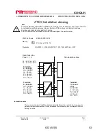
Page 55: ...15 Marking Standards EN 60079 0 2006 EN 60079 11 2007 EN 60079 26 2007 Installation notes The sensor circuit is not infallibly galvanically isolated from the input circuit However the galvanic isolation between the circuits is capable of withstanding a test voltage of 500Vac during 1 minute Non Hazardous Area Hazardous area Zone 0 1 2 II 1 G Ex ia IIC T6 T5 Terminal 41 42 43 44 Uo 9 6 VDC Io 25 mA...

Page 56: ... Certificat ATEX KEMA 06ATEX 0115 Marquage Standards EN 60079 0 2006 EN 60079 11 2007 EN 60079 26 2007 Notes d installation L isolation galvanique entre le circuit du capteur et le circuit d entrée n est pas infaillible Cependant l isolation galvanique entre les circuits est capable de résister à une tension de test de 500 Vca pendant 1 minute Zone non dangereuse Zone dangereuse Zone 0 1 2 II 1 G ...

Page 57: ...at KEMA 06ATEX 0115 Markierung Richtlinien EN 60079 0 2006 EN 60079 11 2007 EN 60079 26 2007 Installationsvorschriften Die galvanische Trennung zwischen dem Sensorkreis und dem Eingangskreis ist nicht unfehlbar Allerdings ist die galvanische Trennung zwischen den Kreisen so ausgelegt dass diese eine Testspannung von 500 VAC für eine Minute aushält Nicht Ex Bereich Ex Bereich Zone 0 1 2 II 1 G Ex i...

Page 58: ...ummeret ATEX certifikat KEMA 06ATEX 0115 Mærkning Standarder EN 60079 0 2006 EN 60079 11 2007 EN 60079 26 2007 Installationsforskrifter Følerkredsløbet er ikke ufejlbarligt galvanisk isoleret fra indgangskredsløbet men den galvaniske isolation mellem kredsene kan modstå en testspænding på 500 VAC i 1 minut Ikke Ex område Ex område Zone 0 1 2 II 1 G Ex ia IIC T6 T5 Klemme 41 42 43 44 Uo 9 6 VDC Io ...

Page 59: ...tors for analogue and digital signals as well as HART signals A wide product range with both loop powered and universal isolators featuring linearisation inversion and scaling of output signals PC or front programmable modules with universal options for input output and supply This range offers a number of advanced features such as process calibration linearisation and auto diagnostics A wide sele...

Page 60: ...1225 West Bernardo Court Suite A San Diego California 92127 sales prelectronics fr tel 33 0 4 72 14 06 07 fax 33 0 4 72 37 88 20 sales prelectronics de tel 49 0 208 62 53 09 0 fax 49 0 208 62 53 09 99 sales prelectronics it tel 39 02 2630 6259 fax 39 02 2630 6283 sales prelectronics es tel 34 93 311 01 67 fax 34 93 311 08 17 sales prelectronics se tel 46 0 3149 9990 fax 46 0 3149 1590 sales prelec...

Reviews: