BI-DIRECTIONAL TOOL TURRET
19
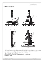
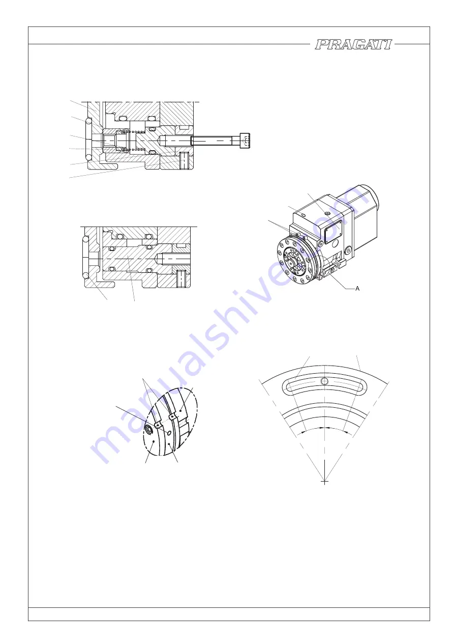
6.3 Replacement of Coolant valve Button (poppet).
Fig 6.3d
Main Body
Coolant Ring
Coolant Flange
Marking groove in line with
coolant flange and Coolant Ring
Marker settings for working position
Insert suitable rod and use
it as a handle for the
adjustment of angular
position of Coolant ring
M4x40 for pulling
Coolant Poppet (44) rubs against coolant ring during indexing; and is liable to wear. Provision has been to
made replace the button, without removing the Tool disc from the turret.
For replacement , Loosen clamps (110), and move coolant ring to align the reference marks in line with the
corresponding mark on the body as shown in fig (fig 6.3f). Remove the Grub (47). Use M4x6 screw for removing
the poppet Assembly. Change the poppet and reassemble it.
Fig 6.3b
Fig 6.3a
IMB50052014
110
103
79,56
Fig 6.3c
Fig 6.3e
20°
20°
22
50
27
44
48
43
49
47
26
98
Summary of Contents for BTP-50
Page 1: ...INSTRUCTION MANUAL B T P 50 BI DIRECTIONAL TOOL TURRET IMB50052014 ...
Page 2: ......
Page 4: ......
Page 31: ......


