GENERAL PUMP
A member of the Interpump Group
KT24A/28A/30A/32A/36A/40A SERIES
Page 11
2.2 REPAIRING HYDRAULIC PARTS
2.2.1 Dismantling the Head - Valve Units
Operations are limited to inspection or replacement of valves, if necessary and, however, at the intervals
indicated in the “Preventative Maintenance” table in chapter 11 of the use and maintenance manual. The
valve units are assembled vertically inside the head.
Operate as follows to extract them:
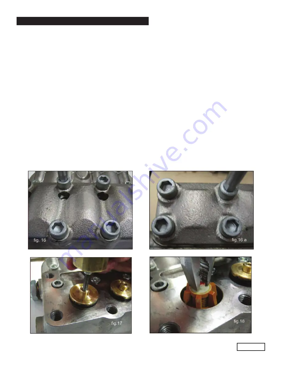
• Unscrew the 8 M14x40 suction valve cover fastening screws and the 8 m12x35 outlet valve cover fastening
screws (fig, 16 and 16a) using the extractor hammer p/n F26019400 combined with tool F27726200 extract
• The KT24A, 28A, 30A, 32A suction and outlet valve units and KT36A or 40A inlet valve units using a
simple tool as indicated in fig. 18
• Extract the KT36 or KT40 pump suction valve units using an extractor hammer part #F26019400 combined
with tool #F27513600 (fig. 19).
Ref 300943 Rev.A
03-14


