12
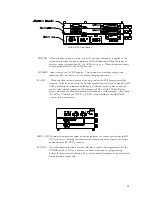
Model 5700 Transmitter
POWER -When the slide switch is moved to the ON position, and power is applied to the
selected synthesizer, the power indicator LED will illuminate. When the internal
battery voltage is greater than 8V, the LED glows green. When the internal battery
voltage drops below 8V, the LED glows red.
CHARGE -Input jack for the AC/DC adapter. This section also contains a charge state
indicator LED. See Section 7.2 for battery charging operation.
BAND
- When the slide switch is moved to the up position, the PCS Synthesizer will be
selected. In the down position, the Cellular Synthesizer is selected. A green BAND
LED will illuminate to indicate which band is selected for the operation and the
status of the selected synthesizer. The respective PCS or CELL LED will glow
green only when the selected synthesizer is locked on a valid frequency. (Substitute
“GSM” for “Cellular” and “DCS” for “PCS” when refering to the GSM/DCS
version of the transmitter.)
AMPL ADJ -Turning this adjustment screw clockwise increases the output power from the RF
OUT connector. Turning this adjustment counter-clockwise decreases the output
power from the RF OUT connector.
TUNING -The individual synthesizers must be selected in order to be programmed. Set the
POWER switch to ON and position the band switch prior to programming.
Follow the Instructions in Section 8.0 to set the desired frequency using an external
controller and a serial cable.


