PREBENA
Wilfried Bornemann GmbH & Co. KG
BEFESTIGUNGSTECHNIK
– FASTENING TECHNOLOGY
9
6.5
Connection for secondary use of the emitted thermal energy
The heat emitted by the compressor cooler can be re-used. The discharged air
contains heat and can be used at the compressor site or in another building area as
air heating. If the latter is being considered, then the collection hood / duct
component for transporting the expelled air must have a greater cross sectional area
than the radiator. It is also necessary to further convey the air using a mechanical
ventilator, to ensure a constant flow rate of air.
The collection hood / duct component directly above the radiator must be removable
for inspection purposes.
6.6
Connection to the power supply
The permissible voltage fluctuations in the power supply should correspond to the
data specified in the included manual.
Electrical cables must meet all safety standards and must have a cross-section that
is in keeping with the power consumption of the compressor. All electrical
connections must be realised by a qualified electrician. The compressor must be
connected to the power supply by means of a fixed connection with appropriate
insulation.
The compressor is equipped with an on/off switch for maintenance and repairs.
The compressor must be properly earthed. Connect the protective conductor of the
power cable to the PE connection (switch cabinet) in accordance with IEC 60204-1
requirements.
The earthing wire must have a solid core copper with a cross section as shown in
Appendix B
.
In accordance with IEC 60204-1, the power supply must have a circuit breaker.
The power supply to the compressor must be equipped with a circuit breaker (fuse) to
protect the compressor against short circuits. This must be designed to comply with
the emergency circuit breaker.
The compressors are suitable for use with a three phase power supply (400 V, 50
Hz), with a tolerance of 10% or 1%. The electric motor has a star-delta circuit. The
voltage across the entire control and signalling circuit is 24 volts AC.
6.7
Schematic circuit diagrams for the compressors can be found in
Appendix E
.
Summary of Contents for SK-15-10
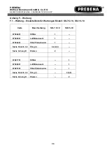
Page 33: ...PREBENA Wilfried Bornemann GmbH Co KG BEFESTIGUNGSTECHNIK FASTENING TECHNOLOGY 33 ANHANG...
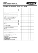
Page 35: ...PREBENA Wilfried Bornemann GmbH Co KG BEFESTIGUNGSTECHNIK FASTENING TECHNOLOGY 35...
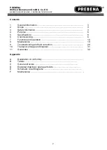
Page 36: ...PREBENA Wilfried Bornemann GmbH Co KG BEFESTIGUNGSTECHNIK FASTENING TECHNOLOGY 36...
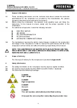
Page 122: ...PREBENA Wilfried Bornemann GmbH Co KG BEFESTIGUNGSTECHNIK FASTENING TECHNOLOGY 33 APPENDIX...
Page 127: ...PREBENA Wilfried Bornemann GmbH Co KG BEFESTIGUNGSTECHNIK FASTENING TECHNOLOGY 38...
Page 128: ...PREBENA Wilfried Bornemann GmbH Co KG BEFESTIGUNGSTECHNIK FASTENING TECHNOLOGY 39...
Page 214: ...PREBENA Wilfried Bornemann GmbH Co KG BEFESTIGUNGSTECHNIK FASTENING TECHNOLOGY 33 ANNEXE...
Page 219: ...PREBENA Wilfried Bornemann GmbH Co KG BEFESTIGUNGSTECHNIK FASTENING TECHNOLOGY 38...
Page 220: ...PREBENA Wilfried Bornemann GmbH Co KG BEFESTIGUNGSTECHNIK FASTENING TECHNOLOGY 39...


