PreciseFlex_Robot
112
Replacing the Robot Controller
DANGER:
Before replacing the Robot Controller, the AC power should be
removed.
Tools Required:
1. 2.5mm hex driver or hex L wrench
2. 2.0mm hex driver or hex L wrench
3. Small flat bladed screw driver, with 1.5mm wide blade typ
4. M5 socket driver or M5 open end wrench or pliers
Spare Parts Required:
1. Guidance G1400B Controller PN P/N G1X0-EA-B1400-1
Prior to replacing the controller, the user may wish to make copies of both the robot PAC files, and any
project files to a PC, using a procedure similar to that described for loading a project in the Software
Reference Section.
To replace the Robot Controller the user must:
1. Turn off the robot power and remove the AC power cord.
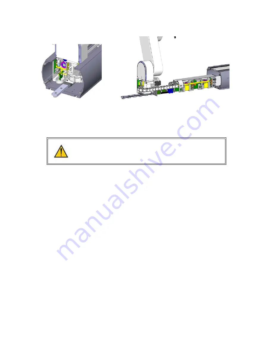
2. Remove the Inner Link Cover by removing the 4 M3 X 20 SHCS that attach the cover.
3. Remove the upper circuit board by removing 4 M2.5 X 6mm screws.
4. Unplug the cables from upper circuit board
5. Remove the lower circuit board by removing 4 M2.5 X 16mm standoffs with an M5 socket driver.
6. Unplug the cables from the lower circuit board. Use a small flat bladed screwdriver to gently
release the 3 zero-insertion-force (ZIF) flat flexible cable (FFC) connector compression lids.
7. Check the jumpers on the replacement CPU board (top board) per the photo below.
8. Re-attach the harness and replace the circuit boards. Refer to the schematics section above for
connector labeling on the circuit boards. Be careful that the 2 pin plug from the brake release
switch plugs into the lower board and the 2 pin plug on the pigtail from the lower board plugs into
Summary of Contents for PF3400
Page 8: ......
Page 32: ...PreciseFlex_Robot 24 Appendix B TUV Verification of PF400 Collision Forces...
Page 33: ...Introduction to the Hardware 25...
Page 34: ...PreciseFlex_Robot 26...
Page 35: ...Introduction to the Hardware 27...
Page 37: ...Introduction to the Hardware 29 Appendix C Table A2 from ISO TS 15066 2016...
Page 38: ...PreciseFlex_Robot 30 Table A2 Continued...
Page 41: ...Introduction to the Hardware 33 PF400 500gm Safety Circuits PF3400 3kg Safety Circuits...
Page 45: ...Installation Information 37...
Page 46: ...PreciseFlex_Robot 38...
Page 47: ...Installation Information 39...
Page 48: ...PreciseFlex_Robot 40...
Page 54: ...PreciseFlex_Robot 46 Schematic System Overview...
Page 55: ...Hardware Reference 47 Schematic FFC Boards Revision B PF400...
Page 56: ...PreciseFlex_Robot 48...
Page 57: ...Hardware Reference 49 Schematic FFC Boards Revision C PF400...
Page 58: ...PreciseFlex_Robot 50 Schematic FFC Boards 3kg PF400...
Page 59: ...Hardware Reference 51...
Page 60: ...PreciseFlex_Robot 52 Schematic Safety System Overview PF400 CAT3...
Page 61: ...Hardware Reference 53...
Page 62: ...PreciseFlex_Robot 54 Controller Power Amplifier Connectors Control Board Connectors...
Page 63: ...Hardware Reference 55 Gripper and Linear Axis Controller Connectors...
Page 64: ...PreciseFlex_Robot 56...
Page 65: ...Hardware Reference 57...
Page 66: ...PreciseFlex_Robot 58 Schematic Slip Ring for 60N Gripper...
Page 67: ...Hardware Reference 59...
Page 68: ...PreciseFlex_Robot 60...
Page 69: ...Hardware Reference 61...
Page 70: ...PreciseFlex_Robot 62...
Page 71: ...Hardware Reference 63...
Page 72: ...PreciseFlex_Robot 64...
Page 73: ...Hardware Reference 65 Motor 60N Gripper...
Page 74: ...PreciseFlex_Robot 66...
Page 106: ...PreciseFlex_Robot 98 b The CALPP application takes about 1 minute to run...
Page 124: ...PreciseFlex_Robot 116 Wiring for 60N Gripper with Battery Pigtail Wiring for Pneumatic Gripper...
Page 125: ...117 Wiring for Vacuum Gripper Wiring for Vacuum Pallet Gripper...


