Introduction to the Hardware
5
Optional Linear Axis Module
The PF400 and PF3400 robots may be attached to an optional Linear Axis Module. The Linear Axis
Module may be ordered in 1000mm, 1500mm and 2000mm travel distances. The module length is about
380mm longer than the travel distance. All cables and controls are contained inside the Linear Axis
Module, which is equipped with drip proof covers and tape seals. Power entry, a power switch, Pendant,
and IO connectors are extended from the base of the robot to the end cap of the Linear Axis Module. The
Linear Axis Module is driven by a servo amplifier located in the carriage. This servo amp gets both power
and commands from the controls in the robot, so the Linear Axis Module must be slaved to a robot in
order to work, and cannot be purchased as a standalone module at this time.
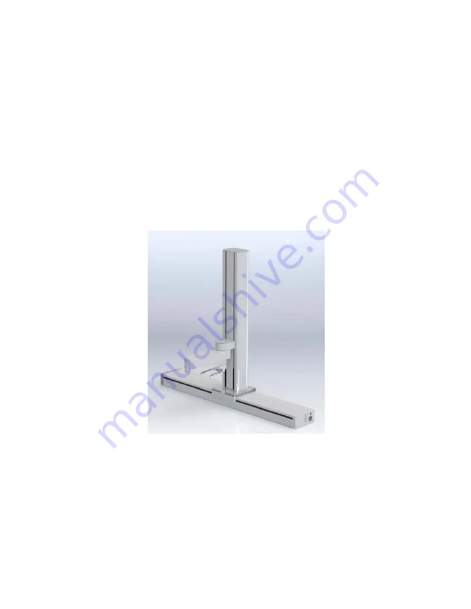
The picture below shows a 750mm vertical travel PF400 on a 1000mm Linear Axis Module. The robot is
positioned in the middle of travel, which is defined as the zero position in the linear axis. The robot may
be mounted in this orientation, in which case the linear axis moves along the Y axis in the robot’s
coordinate system with the linear axis extending the robot’s Y axis by plus or minus 500mm. The robot
may also be rotated 90 degrees so that it faces the connector end cap of the Linear Axis. In this case the
Linear Axis extends the robot’s X axis travel, if the appropriate SW parameter is changed. See the
Software Reference section.
Mounting of Robot and Linear Axis Module
The Robot Base Plate contains a mounting hole pattern for 4 M6 Screws along with reference surfaces
for locating the robot on a table or work cell surface. The Linear Axis Module contains mounting patterns
for both M6 and ¼-20 screws. See Installation section for details.
Summary of Contents for PF3400
Page 8: ......
Page 32: ...PreciseFlex_Robot 24 Appendix B TUV Verification of PF400 Collision Forces...
Page 33: ...Introduction to the Hardware 25...
Page 34: ...PreciseFlex_Robot 26...
Page 35: ...Introduction to the Hardware 27...
Page 37: ...Introduction to the Hardware 29 Appendix C Table A2 from ISO TS 15066 2016...
Page 38: ...PreciseFlex_Robot 30 Table A2 Continued...
Page 41: ...Introduction to the Hardware 33 PF400 500gm Safety Circuits PF3400 3kg Safety Circuits...
Page 45: ...Installation Information 37...
Page 46: ...PreciseFlex_Robot 38...
Page 47: ...Installation Information 39...
Page 48: ...PreciseFlex_Robot 40...
Page 54: ...PreciseFlex_Robot 46 Schematic System Overview...
Page 55: ...Hardware Reference 47 Schematic FFC Boards Revision B PF400...
Page 56: ...PreciseFlex_Robot 48...
Page 57: ...Hardware Reference 49 Schematic FFC Boards Revision C PF400...
Page 58: ...PreciseFlex_Robot 50 Schematic FFC Boards 3kg PF400...
Page 59: ...Hardware Reference 51...
Page 60: ...PreciseFlex_Robot 52 Schematic Safety System Overview PF400 CAT3...
Page 61: ...Hardware Reference 53...
Page 62: ...PreciseFlex_Robot 54 Controller Power Amplifier Connectors Control Board Connectors...
Page 63: ...Hardware Reference 55 Gripper and Linear Axis Controller Connectors...
Page 64: ...PreciseFlex_Robot 56...
Page 65: ...Hardware Reference 57...
Page 66: ...PreciseFlex_Robot 58 Schematic Slip Ring for 60N Gripper...
Page 67: ...Hardware Reference 59...
Page 68: ...PreciseFlex_Robot 60...
Page 69: ...Hardware Reference 61...
Page 70: ...PreciseFlex_Robot 62...
Page 71: ...Hardware Reference 63...
Page 72: ...PreciseFlex_Robot 64...
Page 73: ...Hardware Reference 65 Motor 60N Gripper...
Page 74: ...PreciseFlex_Robot 66...
Page 106: ...PreciseFlex_Robot 98 b The CALPP application takes about 1 minute to run...
Page 124: ...PreciseFlex_Robot 116 Wiring for 60N Gripper with Battery Pigtail Wiring for Pneumatic Gripper...
Page 125: ...117 Wiring for Vacuum Gripper Wiring for Vacuum Pallet Gripper...


