Hardware Reference
75
Digital Outputs in the Outer Link
In the Revision C and 3kg versions of the PF400 the motor interface board in the outer link can be
connected by means of a flat ribbon cable to the controller digital inputs and digital outputs, providing
support for both pneumatic and vacuum grippers where desired. The schematic for this interconnect
board can be found in the schematics section labeled Schematic: Revision C of FFC Boards.
For the 3kg version of the FFC boards, a jumper has been added to the MIDS4 power interface board
located on the vertical wall of the inner link. This jumper connects the signals in the IO cable running to
the outer link to either the IO port of the controller OR the RS485 port of the controller. When this jumper
is placed in the “IO” position the innermost connector on the IO cable should be plugged into the J4 motor
interface board in the outer link which connects the IO signals. These signals are then available to
control solenoids for both air and vacuum grippers. When the jumper is placed in the “RS485” position,
the outermost connector on the IO cable in the outer link should be plugged into the GSB gripper
controller board.
<Insert images of J4 motor interface board in 2 solenoid config and RS485 config>
Ethernet Interface
PreciseFlex robots include an Ethernet switch that implements two 10/100 Mbit Ethernet ports. This
capability was designed to permit the controller to be interfaced to multiple Ethernet devices such as
other Precise controllers or robots, remote I/O units and Ethernet cameras. The Ethernet switch
automatically detects the sense of each connection, so either straight-thru or cross-over cables can be
used to connect the controller to any other Ethernet device.
Due to limited space on the Facilities Panel, only one of the two Ethernet ports is available via an external
RJ45 connector. This external Ethernet port is typically used to interface the robot to a PC. The second
Ethernet port is only available inside the inner link of the robot. In some cases it may be used to connect
an Ethernet camera that is mounted on the robot.
In this case, a PC that is connected to the Ethernet plug on the Facilities Panel can communicate with the
robot’s controller as well as receive images from an arm-mounted camera. (For the initial release of this
robot, arm mounted cameras are not supported.)
If a camera is mounted in the workcell, an external Ethernet switch must be added to connect these
cameras and the robot to a PC.
See the
Setup and Operation Quick Start Guide
for instructions on setting the IP address for the
controller.
RS-232 Serial Interface
The PreciseFlex robot includes a standard RS-232 serial line equipped with hardware or software flow
control. However this port is only available on the G1400B controller in the inner link of the robot and is
not brought out to any outside connector on this robot. This port can be used to communicate to the
system serial console or can be connected to external equipment for general communication purposes.
When used for general communications, this port is referenced as device "/dev/com1" within the
Guidance Programming Language (GPL).
Summary of Contents for PF3400
Page 8: ......
Page 32: ...PreciseFlex_Robot 24 Appendix B TUV Verification of PF400 Collision Forces...
Page 33: ...Introduction to the Hardware 25...
Page 34: ...PreciseFlex_Robot 26...
Page 35: ...Introduction to the Hardware 27...
Page 37: ...Introduction to the Hardware 29 Appendix C Table A2 from ISO TS 15066 2016...
Page 38: ...PreciseFlex_Robot 30 Table A2 Continued...
Page 41: ...Introduction to the Hardware 33 PF400 500gm Safety Circuits PF3400 3kg Safety Circuits...
Page 45: ...Installation Information 37...
Page 46: ...PreciseFlex_Robot 38...
Page 47: ...Installation Information 39...
Page 48: ...PreciseFlex_Robot 40...
Page 54: ...PreciseFlex_Robot 46 Schematic System Overview...
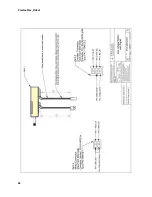
Page 55: ...Hardware Reference 47 Schematic FFC Boards Revision B PF400...
Page 56: ...PreciseFlex_Robot 48...
Page 57: ...Hardware Reference 49 Schematic FFC Boards Revision C PF400...
Page 58: ...PreciseFlex_Robot 50 Schematic FFC Boards 3kg PF400...
Page 59: ...Hardware Reference 51...
Page 60: ...PreciseFlex_Robot 52 Schematic Safety System Overview PF400 CAT3...
Page 61: ...Hardware Reference 53...
Page 62: ...PreciseFlex_Robot 54 Controller Power Amplifier Connectors Control Board Connectors...
Page 63: ...Hardware Reference 55 Gripper and Linear Axis Controller Connectors...
Page 64: ...PreciseFlex_Robot 56...
Page 65: ...Hardware Reference 57...
Page 66: ...PreciseFlex_Robot 58 Schematic Slip Ring for 60N Gripper...
Page 67: ...Hardware Reference 59...
Page 68: ...PreciseFlex_Robot 60...
Page 69: ...Hardware Reference 61...
Page 70: ...PreciseFlex_Robot 62...
Page 71: ...Hardware Reference 63...
Page 72: ...PreciseFlex_Robot 64...
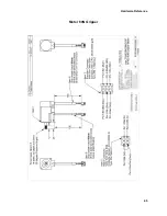
Page 73: ...Hardware Reference 65 Motor 60N Gripper...
Page 74: ...PreciseFlex_Robot 66...
Page 106: ...PreciseFlex_Robot 98 b The CALPP application takes about 1 minute to run...
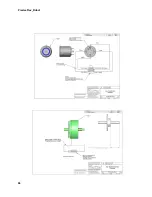
Page 124: ...PreciseFlex_Robot 116 Wiring for 60N Gripper with Battery Pigtail Wiring for Pneumatic Gripper...
Page 125: ...117 Wiring for Vacuum Gripper Wiring for Vacuum Pallet Gripper...


