Helios PD2-6080/PD2-6081 Modbus
®
Scanners
Instruction Manual
9
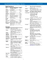
Math Functions
Name
Math Operation (Examples)
(P = Adder, F = Factor)
Setting
Addition
(PV1+PV2+P)*F
Sunm
Difference
(PV1-PV2+P)*F
diF
Absolute
difference
((Abs(PV1- PV2)+P)*F
diFAbS
Average
(((PV1+PV2)/2)+P)*F
AvG
Multiplication
((PV1*PV2)+P)*F
Nmulti
Division
((PV1/PV2)+P)*F
divide
Max PV
Max value of all selected PVs
Hi-pv
Min PV
Min value of all selected PVs
Lo-pv
Draw
((PV1/PV2)-1)*F
drAuw
Weighted
average
((PV2-PV1)*F)+PV1
uwavg
Ratio
(PV1/PV2)*F
Ratio
Concentration
(PV1/(PV1+PV2))*F
Concen
Math 2
Math on other math channels
Nmath2
Programmable
Constants
Constant P (Adder): -99.999 to 999.999,
default: 0.000
Constant F (Factor): 0.001 to 999.999,
default: 1.000
General
Input/output
Modbus RTU over RS-485
Two analog inputs (4-20 mA,
10 V)
Display
Dual-line: 1.8" (46 mm) high, red LEDs
6 digits per line (-99999 to 999999), with
lead zero blanking
Display
Intensity
Eight user selectable intensity levels.
Default value is six.
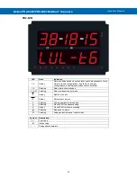
LED Status
Indicators
on page
details.
Overrange
Display flashes
999999
Underrange
Display flashes
-99999
Programming
Methods
Four programming buttons, digital inputs,
PC and ScanView software, or Modbus
registers.
Max/Min
Display
Max/min readings are stored until reset by
the user or when power to the scanner is
turned off. User can reset by front panel
pushbuttons, digital input, or via Modbus
registers.
Rounding
Select 1, 2, 5, 10, 20, 50, or 100
(e.g. rounding = 10, value = 123.45,
display = 123.50).
Password
Three programmable passwords restrict
modification of programmed settings.
Pass 1: Allows use of function keys and
digital inputs
Pass 2: Allows use of function keys, digital
inputs and editing set/reset points
Pass 3: Restricts all programming, function
keys, and digital inputs.
Non-Volatile
Memory
All programmed settings are stored in non-
volatile memory for a minimum of ten
years, with or without power.
Power
Options
85-265 VAC 50/60 Hz; 90-265 VDC, 20 W max;
12-24 VDC, 12-24 VAC, 15 W max.
Powered over USB for configuration only.
Fuse
Required external fuse: UL Recognized,
5 A max, slow blow; up to 6 scanners may
share one 5 A fuse.
Isolation
4 kV input/output-to-power line
500 V input-to-output or output-to-P+ supply
Overvoltage
Category
Installation Overvoltage Category II: Local
level with smaller transient overvoltages
than Installation Overvoltage Category III.
Environmental
Operating temperature range:
-40 to 65°C (-40 to 149°F)
Storage temperature range:
-40 to 85°C (-40 to 185°F)
Relative humidity:
0 to 90% non-condensing
Note: Printed circuit boards are conformally
coated.
Connections
Power, signal, relays, mA out: Removable
screw terminal blocks accept 12 to 22
AWG wire.
RS-485: Removable screw terminal block
accepts 16 to 30 AWG wire.
Digital I/O: Non-removable screw terminal
blocks accept 16 to 30 AWG wire.
Enclosure
UL Type 4X, IP65 rated. Polycarbonate &
glass blended plastic case, color: gray.
Includes four PG11 through-hole conduit
openings, with two factory installed PG11,
IP68, black nylon threaded hole plugs with
backing nuts.
Mounting
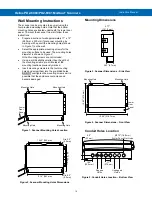
Wall Mounting:
Four (4) mounting holes provided for
mounting scanner to wall. See
on page
for
additional details.
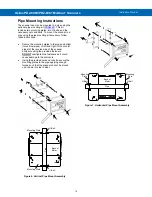
Pipe Mounting:
Optional pipe mounting kit (PDA6260)
allows for pipe mounting. Sold separately.
See
on page
for additional details.
Tightening
Torque
Power, signal, relays, mA out terminals:
5 lb-in (0.56 Nm)
Digital I/O and RS-485:
2.2 lb-in (0.25 Nm)
Overall
Dimensions
10.63" x 12.59" x 4.77"
(270 mm x 319.7 mm x 121.2 mm)
(W x H x D)
Weight
6.10 lbs (2.76 kg)
Warranty
3 years parts & labor. See Warranty
Information and Terms & Conditions on
for complete details.


