background image

PRECISION DIGITAL CORPORATION 

Javelin D • Model PD644 

Instruction Manual 

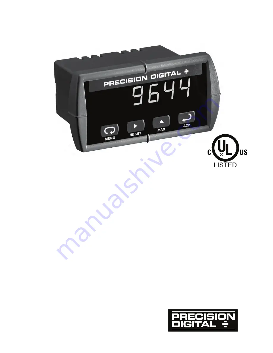
Measures DC Voltage up to 300 VDC

4 Digit Display, 0.56" (14 mm) High, Red LEDs

Maximum/Minimum 

Display

NEMA 4X, IP65 Front

4-20 mA Transmitter

Universal Power Supply 85-265 VAC

12-36 VDC/12-24 VAC Power Option

Two 

Relays 

Option

RS-485 Serial Communication

Modbus

®

 RTU Option

Copy Meter Settings to Other Meters

www.

GlobalTestSupply

.com

Find Quality Products Online at:

sales@GlobalTestSupply.com

Summary of Contents for Javelin D PD644

Page 1: ...m High Red LEDs Maximum Minimum Display NEMA 4X IP65 Front 4 20 mA Transmitter Universal Power Supply 85 265 VAC 12 36 VDC 12 24 VAC Power Option Two Relays Option RS 485 Serial Communication Modbus R...

Page 2: ...ents hereof and specifically disclaims any implied warranties of merchantability or fitness for a particular purpose Registered Trademarks Modbus is a registered trademark of Schneider Automation Inc...

Page 3: ...Model Options Installed PD644 6R3 14 24 VDC Transmitter Supply PD644 6R5 14 2 Relays 24 VDC Supply PD644 7R3 04 None PD644 7R5 04 2 Relays All models may be powered from AC or DC See Specifications fo...

Page 4: ...nication 14 Relay Output Connections 14 Switching Inductive Loads 15 4 20 mA Output Signal Connections 16 SETUP AND PROGRAMMING 17 Front Panel Buttons and Status LED Indicators 18 Display Functions an...

Page 5: ...u SElc 40 Display Intensity inty 41 Meter Copy Function Copy 42 Internal Calibration ICal 44 OPERATION 46 Front Panel Buttons Operation 46 Maximum and Minimum Readings 47 MOUNTING DIMENSIONS 48 TROUBL...

Page 6: ...20 mA Transmitter Powered by Meter 16 Figure 9 4 20 mA Transmitter Powered Externally 16 Figure 10 Meter Copy Connection 42 Figure 11 Meter Dimensions Side View 48 Figure 12 Case Dimensions Top View...

Page 7: ...and minimum measured voltages stored until reset by the user or until power to the meter is turned off PASSWORD Programmable password restricts modification of programmed settings NON VOLATILE MEMORY...

Page 8: ...m H x W x D WEIGHT 9 oz 255 g Including options WARRANTY 3 years parts and labor EXTENDED WARRANTY 1 or 2 years refer to Price List for details Voltage Measurement Input INPUT 0 to 300 VDC ACCURACY 0...

Page 9: ...panel buttons or serial communication Automatic reset only non latching Automatic plus manual reset at any time non latching Manual reset only at any time latching Manual reset only after alarm condi...

Page 10: ...imum 24 VDC 10 700 OUTPUT LOOP RESISTANCE 35 VDC external 100 1200 Serial Communications METER ADDRESS PDC protocol 0 99 Modbus protocol 1 247 BAUD RATE 300 19 200 bps TRANSMIT TIME DELAY Programmable...

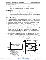
Page 11: ...ntain Type 4X rating 0 06 1 5 mm steel panel 0 16 4 1 mm plastic panel x Remove the two mounting brackets provided with the meter back off the two screws so that there is 6 4 mm or less through the br...

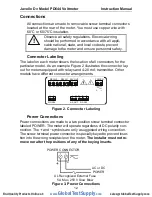
Page 12: ...nsmitter Other models have different connector arrangements 24V OUT 2 1 P P V V 1 2 SIGNAL mA OUT D D I I G 3 4 1 2 5 RS 485 COM NO NO NC NC COM 4 3 6 5 2 1 RELAY2 RELAY1 POWER 2 1 Figure 2 Connector...

Page 13: ...be at ground potential Be sure to ob serve the correct polarity The reversal of polarity can result in damage to the meter and associated data communications equipment and can expose personnel to ele...

Page 14: ...en D and D that matches the characteristic impedance of the cable A typical value for termination resistors is 120 RS 485 CONNECTOR 1 3 2 G D D Data Common Data Data Shield Twisted Pair RS 485 CONNECT...

Page 15: ...relay rating is 1 14 HP 50 W at 115 230 VAC 2 Use capacitors rated for 250 VAC 3 RC networks may affect load release time of solenoid loads Check to confirm proper operation 4 Install the RC network a...

Page 16: ...ernal power supply optional available at the screw terminal connector labeled 24V OUT or from an external power supply I mA OUT 2 1 I Remote Display Chart Recorder etc P 24V OUT 1 2 P Figure 9 4 20 mA...

Page 17: ...nt used at the factory is certified to NIST standards Overview All setup and programming functions are done with the front panel but tons There are no jumpers involved in the setup process of the mete...

Page 18: ...at any time x Press the Right arrow button to move to the next digit during digit programming x Press the Up arrow button to scroll through the menus decimal point or to increment the value of a digi...

Page 19: ...atching Set relay for latching operation L CL Latching cleared Set relay for latching operation with manual reset only after alarm condition has cleared Altr Alternate Set relays for alternation contr...

Page 20: ...er the Program menu Cal Calibrate Enter the Calibrate menu scal Scale Enter the Scale menu inp1 Input 1 Calibrate input 1 signal or program input 1 value dis1 Display 1 Program display 1 value inp2 In...

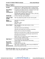
Page 21: ...o scroll main menu 237 7 setu prog pass Run Mode x Press Menu at any time to exit and return to Run Mode Changes made to settings prior to pressing Enter Ack are not saved x Changes to the settings ar...

Page 22: ...0 0400 0500 Increment Digit Value Next Setting Select Next Digit Accept Setting Setting Up the Meter setu The Setup menu is used to select 1 Relay operation 2 4 20 mA analog output setup Press the Ent...

Page 23: ...after alarm condi tion has cleared e Alternation control automatic reset only f Off relay and status LED disabled 2 Set point 3 Reset point 4 Fail safe operation a On enabled b Off disabled 5 Time de...

Page 24: ...setup relay 2 is set up in a similar fashion Auto A m LtCH Act1 L CL From Relay 1 Menu Press Enter Ack button to accept setting Press Menu button to exit at any time ALtr oFF Programming Set and Rese...

Page 25: ...ime on oFF Programming Time Delay The On and Off time delays may be programmed for each relay be tween 0 and 199 seconds The relays will transfer only after the condi tion has been maintained for the...

Page 26: ...f on Relay LED Automatic or Manual non latching ACK pressed Relay LED Manual latching ACK pressed Relay LED Manual only after passing below Reset latching with clear ACK pressed Set Reset Automatic no...

Page 27: ...ACK pressed Relay LED Manual latching ACK pressed Relay LED ACK pressed Automatic non latching Manual only after passing above Reset latching with clear For Manual reset mode ACK can be pressed anyti...

Page 28: ...Automatic or Manual non latching ACK pressed Relay LED Manual latching ACK pressed Relay LED Manual only after passing below Reset latching with clear ACK pressed Set Reset Fail safe operation relay...

Page 29: ...Relay LED Automatic or Manual non latching ACK pressed Relay LED Manual latching ACK pressed Relay LED Manual only after passing above Reset latching with clear ACK pressed Fail safe operation relay c...

Page 30: ...the On time delay timer starts and the relay trips when the time delay has elapsed If the signal drops below the set point high alarm before the time delay has elapsed the On time delay timer resets a...

Page 31: ...t Input de energized energized Relay1 Set Relay2 Set Relay1 Relay2 Reset LEDs indicate the relay status Input Input Relay1 Reset Relay2 Reset Relay1 Reset de energized energized de energized energized...

Page 32: ...ut based on display values 2 Sensor break value in mA out1 04 00 Press Enter to Accept Setting dis2 Scale Output 2 dis1 Set Display 1 Value scal 0000 Set Output 1 Value Press Up to Set Digit Value Pre...

Page 33: ...tified to NIST standards x Simply connect the power and signal to the proper terminals and turn the power on No calibration needed when the meter is first re ceived from the factory The Program menu c...

Page 34: ...Set Digit Value Press Right to Select Next Digit Press Menu to Exit at any Time 000 0 Calibrating the Meter Cal The meter can be calibrated to display in convenient engineering units by applying the a...

Page 35: ...ICal The Internal Calibration ICAL menu located in the Advanced features menu is used to recalibrate the voltage input so that the Scaling feature has accurate reference points Recalibration is recomm...

Page 36: ...password to 0000 dis abling the protection Changes to the programmed parameter settings are allowed only with the password set to 0000 If the password entered is incorrect the meter displays LoCd Loc...

Page 37: ...buttons for three sec onds to access the Advanced features of the meter Tip press and hold Right arrow first then press Menu SELc Press Enter Ack to Access Menu or to Accept Setting serl byps Copy Pre...

Page 38: ...time Modbus only Copy Copy Enter copy function send Send Send meter settings to another meter done Done Copy function completed Selc Select Enter the Select menu output intensity out Output Set meter...

Page 39: ...low down the display response to changes in the input signal The filter level may be set anywhere from 2 to 199 Setting filter value to zero disables filter function and bypass setting becomes irrelev...

Page 40: ...Addr bAud trde When using more than one meter in a multi drop mode each meter must be provided with its own unique address The address may be programmed from 00 to 99 for PDC protocol and from 1 to 24...

Page 41: ...om eight brightness levels to accommodate a wide variety of ambient lighting conditions inty Select Display Intensity Level out int3 SELc Press Enter to Accept Setting Press Up to Select Value Press M...

Page 42: ...function must not be en gaged while more that two meters are connected together Cable Assembly Master Clone Co P y Figure 11 Meter Copy Connection Copy Function Requirements To copy settings from one...

Page 43: ...ding data The message done is displayed when copying is completed Copy send Advanced Features done Display Flashes While Sending Press Menu to Exit and Return to Run Mode 6 The Clone meter displays th...

Page 44: ...ter Tip press and hold Right arrow first then press Menu 2 Press the Up arrow button to scroll to the Internal calibration menu and press Enter Ack 3 The meter displays voltage volt Press Enter Ack to...

Page 45: ...even slightly Error Message Err An error message indicates that the calibration process was not suc cessful After the error message is displayed the meter reverts to input 1 allow ing acceptable input...

Page 46: ...ymbol Description Press to enter or exit Programming Mode view settings or exit Max Min display If displaying Max or Min reading press to reset Max or Min reading Press to display Max reading If displ...

Page 47: ...splay maximum reading since the last reset power up 2 Press Up arrow Max again to display the minimum reading since the last reset power up 3 Press Enter Ack to hold Max Min display reading the meter...

Page 48: ...MOUNTING DIMENSIONS 1 76 45mm 0 59 15mm 3 2 81mm 2 45 62mm 3 6 91mm Figure 12 Meter Dimensions Side View 3 61 92mm 2 50 64mm 4 68 119mm Figure 13 Case Dimensions Top View www GlobalTestSupply com Find...

Page 49: ...ttings for troubleshooting purposes Press the Enter Ack button to view the set tings and the Menu button to exit at any time For a description of the diagnostics messages see Advanced Features Menu Di...

Page 50: ...lt Setting User Setting Programming prog Scale Input 1 InP1 000 0 VDC Display 1 Dis1 000 0 Input 2 InP2 200 0 VDC Display 2 Dis2 200 0 Decimal point ddd d 1 decimal place Relay 1 Rly1 Action 1 Act1 Au...

Page 51: ...00 Baud rate baud 2400 Trans delay trde 10 ms Output option on Factory set only Display intensity inty Level 2 Modbus Address addr 247 Parity prty Even Byte to byte timeout tbyt 0 01 sec The byte to b...

Page 52: ...es Menu page 37 2 Press Up arrow to go to Diagnostics menu 3 Press and hold Right arrow Reset for five seconds press Enter Ack when display flashes reset Note If Enter Ack is not pressed within three...

Page 53: ...splay readings Display response is too slow Check filter and bypass values If the display locks up or the meter does not respond at all Cycle the power to restart the microprocessor Relay operation is...

Page 54: ...ate Input Relays Relay 1 Relay 2 Failsafe Delays Action Set Point Reset Point Auto Auto Manual Latch Latch w Clear Alternate Off To Set Point Failsafe 1 Failsafe 2 To Delays Delay 1 Delay 2 On Off Ana...

Page 55: ...o the current value Press Menu or wait 10 seconds to return to Run Mode Pressing Enter Ack will disable the 10 second timeout and continuously display Max or Min Press hold Right arrow and Menu for 3...

Page 56: ...Javelin D Model PD644 Voltmeter Instruction Manual LIM644_E SFT028 Ver 1 0 10 15 www GlobalTestSupply com Find Quality Products Online at sales GlobalTestSupply com...

Reviews: