Javelin D
Ɣ
Model PD644 Voltmeter
Instruction Manual
12
Connections
All connections are made to removable screw terminal connectors
located at the rear of the meter. You must use copper wire with
60°C or 60/75°C insulation.
!
Observe all safety regulations. Electrical wiring
should be performed in accordance with all appli-
cable national, state, and local codes to prevent
damage to the meter and ensure personnel safety.
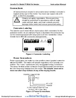
Connector Labeling
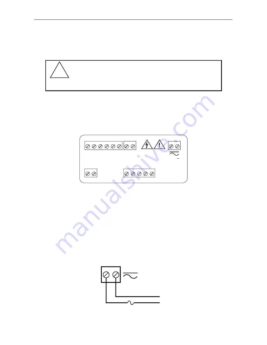
The label on each meter shows the location of all connectors for the
particular model. As an example Figure 2 illustrates the connector lay-
out for meters equipped with relays and 4-20 mA transmitter. Other
models have different connector arrangements.
24V OUT
2
1
P+
P-
V+
V-
1
2
SIGNAL
mA OUT
D+
D-
I
-
I
+
G
3
4
1
2
5
RS-485
COM NO
NO
NC
NC
COM
4
3
6
5
2
1
RELAY2
RELAY1
POWER
2
1
+
Figure 2. Connector Labeling
Power Connections
Power connections are made to a two position screw terminal connector
labeled POWER. The meter will operate regardless of DC polarity con-
nection. The
+
and
-
symbols are only a suggested wiring convention.
The screw terminal power connector is specially keyed to prevent inser-
tion into the wrong receptacle on the meter.
The installer must not re-
move nor alter the positions of any of the keying inserts.
1
2
AC or DC
POWER
UL Recognized External Fuse
5 A Max, 250 V Slow Blow
POWER CONNECTOR
+
-
Figure 3. Power Connections
www.
GlobalTestSupply
.com
Find Quality Products Online at:
sales@GlobalTestSupply.com


