background image

PD8

6

5

 Snoop

e

r Modbus


Se

ria

l In

put Me

te

Ins

truc

tion M

a

nua

l: Re

gis

te

r Ta

ble


75 

Regist

er 

1


Name


A

c

c

ess

Limit

s


or 

Range


2

Data

Ty

p

e


3

Func

tio

Code

(s)


Com

m

en

ts


Num

b

er


A

d

d

res

(hex

403

02


301


(012D

4-

20m

A

 ou

– 

Ov

errange 

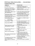
va

lu

e


R

ead 

Wr

it

e


0 t

o

 23

999


Int

e

ger


03, 04, 06,


16


Corresponds to 0.

00

0

 to 23.9

99 

m

A

. Because of hard

w

a

re 

v

a

riations, the actual 

output range is

 de

sig

n

ed t

o

 be at

 l

east

 1.0

0

to

 23.0

00 m

A

403

03


302


(012E)


4-

20m

A

 ou

– 

Underrang

e v

a

lue 

R

ead 

Wr

it

e


0 t

o

 23

999


Int

e

ger


03, 04, 06,


16


Corresponds to 0.

00

0

 to 23.9

99 

m

A

. Because of hard

w

a

re 

v

a

riations, the actual 

output range is

 de

sig

n

ed t

o

 be at

 l

east

 1.0

0

to

 23.0

00 m

A

403

04


303


(012F)


4-

20m

A

 ou

– M

aximum


va

lu

e


allo

w

e

d


R

ead 

Wr

it

e


0 t

o

 23

999


Int

e

ger


03, 04, 06,


16


Corresponds to 0.

00

0

 to 23.9

99 

m

A

. Because of hard

w

a

re 

v

a

riations, the actual 

output range is

 de

sig

n

ed t

o

 be at

 l

east

 1.0

0

to

 23.0

00 m

A

403

05


304


(0130)


4-

20m

A

 ou

– Minimum 

va

lu

e


allo

w

e

d


R

ead 

Wr

it

e


0 t

o

 23

999


Int

e

ger


03, 04, 06,


16


Corresponds to 0.

00

0

 to 23.9

99 

m

A

. Because of hard

w

a

re 

v

a

riations, the actual 

output range is

 de

sig

n

ed t

o

 be at

 l

east

 1.0

0

to

 23.0

00 m

A

403

06


305


(0131)


4-

20m

A

 ou

– Comm. 

B

reak 

va

lu

e


R

ead 

Wr

it

e


0 t

o

 23

999


Int

e

ger


03, 04, 06,


16


Corresponds to 0.

00

0

 to 23.9

99 

m

A

. Because of hard

w

a

re 

v

a

riations, the actual 

output range is

 de

sig

n

ed t

o

 be at

 l

east

 1.0

0

to

 23.0

00 m

A

403

07 – 

403

08


306 – 

3

07


(0132 – 

013

3)


4-

20m

A

 ou

– D

ispl

a

y


Value 1


R

ead 

Wr

it

e


-1999

99 t

o


+9

9

9

99

Long 

03, 04, 16


4-20m

A

 ou

tput scalin

g. Repres

ents

 the di

s

p

la

y

 v

a

lue 

w

ithout the 

decima

l point.


Summary of Contents for PD865

Page 1: ...r Snooper Mode 6 Digit Display 0 56 14 mm High Red LEDs Sunlight Readable Linear Square Root or Programmable Exponent 16 Point Linearization Maximum Minimum Display Type 4X NEMA 4X IP65 Front Universa...

Page 2: ...where malfunctioning could result in personal injury or property loss Anyone using this product for such applications does so at his her own risk Precision Digital Corporation shall not be held liable...

Page 3: ...g 14 Panel Mounting 14 MOUNTING DIMENSIONS 15 Connections 16 Connector Labeling 16 Power Connections 17 Serial Connections 18 Relay Connections 19 Switching Inductive Loads 19 4 20 mA Output Connectio...

Page 4: ...atures Menu Display Messages 53 Display Math Function func 54 Noise Filter filter 55 Noise Filter Bypass bypass 55 Low Flow Cutoff CutofF 55 Analog Output Programming aoutpr 56 4 20 mA Output Calibrat...

Page 5: ...ional Relay Connectors 19 Figure 8 AC and DC Loads Protection 19 Figure 9 Low Voltage DC Loads Protection 20 Figure 10 4 20 mA Output Powered by Meter 21 Figure 11 4 20 mA Output Powered Externally 21...

Page 6: ...w depth 1 8 DIN panel meter enclosure that features a NEMA 4X front panel Data is displayed on an adjustable intensity six digit seven segment LED display The Snooper can be powered from 85 265 VAC or...

Page 7: ...put Calibrated at the factory Recalibration is recommended at least every 12 months MAX MIN DISPLAY Max min readings are stored until reset by the user or when power to the meter is turned off User ca...

Page 8: ...z 227 g 2 relays 9 7 oz 275 g 4 relays 4 20mA Output 24 V supply WARRANTY 3 years parts and labor Operating Modes MASTER Processes data read from a Modbus RTU slave device only one process variable at...

Page 9: ...d Floating point data types DATA TYPE Select the data format that the slave device uses Select between Short integer 2 byte and Long integer 4 byte or floating point 4 byte Signed or Unsigned integer...

Page 10: ...or dddddd FLOAT DECIMAL POINT Select the number of decimals to use for the floating point data expected from the slave or master device this is independent from the display decimal point selection MAT...

Page 11: ...Automatic reset only non latching Automatic manual reset at any time non latching Manual reset only at any time latching Manual reset only after alarm condition has cleared latching Automatic reset Re...

Page 12: ...ANCE Power supply Minimum Maximum 24 VDC 10 700 35 VDC external 100 1200 DATA SOURCE Display Value Maximum Display Value Minimum Display Value or Modbus Register OVERRANGE Programmable mA output for o...

Page 13: ...LE NUMBER E160849 FRONT PANEL UL Type 4X NEMA 4X IP65 panel gasket provided SAFETY INFORMATION CAUTION Read complete instructions prior to installation and operation of the meter WARNING Risk of elect...

Page 14: ...s Clearance allow at least 4 102 mm behind the panel for wiring Panel thickness 0 04 0 25 1 0 mm 6 4 mm Recommended minimum panel thickness to maintain Type 4X rating 0 06 1 5 mm steel panel 0 16 4 1...

Page 15: ...PD865 Snooper ModbusSerial Input Meter Instruction Manual 15 MOUNTING DIMENSIONS 865SideViewDim Figure 2 Meter Dimensions Side View Figure 3 Case Dimensions Top View...

Page 16: ...on for all line voltage connections Observe all safety regulations Electrical wiring should be performed in accordance with all applicable national state and local codes to prevent damage to the meter...

Page 17: ...tions are made to a two terminal connector labeled POWER in Figure 2 The meter will operate regardless of DC polarity connection The and symbols are only a suggested wiring convention 1 2 AC or DC POW...

Page 18: ...nded to protect the data signals from electrical interference For long wire runs it is good practice to terminate the bus at both ends with a resistor connected between D and D that matches the charac...

Page 19: ...tor capacitor RC networks assembled by the user or purchased as complete assemblies Refer to the following circuits for RC network assembly and installation L O A D or Figure 8 AC and DC Loads Protect...

Page 20: ...oltage DC Loads Protection RC Networks Available from Precision Digital RC networks are available from Precision Digital and should be applied to each relay contact switching an inductive load Part nu...

Page 21: ...he 4 20 mA output may be powered from an internal power supply optional or from an external power supply Remote Display Chart Recorder etc P 2 1 P 24V OUT 1 2 mA OUT RLY2 RLY1 3 4 5 6 I I NO COM NO CO...

Page 22: ...ed from the factory The 4 20 mA output is factory calibrated prior to shipment The calibration equipment is certified to NIST standards Overview There are no jumpers involved in the meter setup proced...

Page 23: ...Programming Mode at any time Press the Right arrow button to move to the next digit during digit programming Press the Up arrow button to scroll through the menus decimal point or to increment the va...

Page 24: ...Enter the Number of PVs to be read from the slave device s SLAv Id Slave ID Enter the Slave ID menu for Master and Snooper modes Enter the Slave ID or address for Slave mode Id Pv1 PV1 ID Enter the Sl...

Page 25: ...x65536 digits for the Register Number by pressing the Right arrow in Register Number menu Data 1 Data Type Enter the Data type menu for PV1 Short Short Integer Select Short Integer as the data type to...

Page 26: ...ial Serial Enter Serial menu Baud Baud Enter the Baud rate menu 300 300 baud Select 300 baud for all serial communications 600 600 baud Select 600 baud for all serial communications 1200 1200 baud Sel...

Page 27: ...lay1 Relay 1 setup Similar menus for Relays 2 to 4 are not shown here Act1 Action1 Set relay 1 action automatic latching etc Auto Automatic Set relay for automatic reset A nman Auto manual Set relay f...

Page 28: ...turns off when Communications Break detected on On Action Relay turns on when Communications Break detected Aout Analog Output Scaling Enter the Analog Output Scaling menu diS 1 Display 1 Program the...

Page 29: ...enu every time a setting is accepted by pressing Enter Ack Setting Numeric Values The numeric values are set using the Right and Up arrow buttons Press Right arrow to select next digit and Up arrow to...

Page 30: ...e PLC DCS etc The data sent to it by the master is scaled displayed and used to operate the relays and 4 20 mA output All parameters are accessible via the Slave Mode Register Table on page 69 3 Snoop...

Page 31: ...r funCod fun 03 fun 04 data 1 short long float binary bcd unsigd signed 1234 4321 2143 3412 The last two Byte Order settings are not available for Short Integer data types reg nbr Enter Register Numbe...

Page 32: ...ling mode the PD865 Master always displays PV1 the first value polled The baud rate for polling more than 2 variables should be set to be greater than 4800 bps A faster baud rate will produce fewer co...

Page 33: ...47 247 PV1 247 PV2 247 PV3 247 Register Number 30003 30017 Reg PV1 30001 Reg PV2 30003 2 Reg Reg PV3 30017 2 Reg Data Type Long integer Binary Signed Long Long Byte Order 1234 1234 1234 Polling Time 2...

Page 34: ...efined parameters Press Enter Ack to Make Selections Press Up Arrow to Scroll Through Choices Press Menu to Exit at any Time Press Right Arrow to display and change the setting for the number of digit...

Page 35: ...ttings are not available for Short Integer data types SLAv 1d Enter Process Variable Value Snoopr funCod fun 03 fun 04 reg nbr Enter Register Number Value 5 dig 6 dig Notes 1 To minimize the possibili...

Page 36: ...Make Selections Press Up Arrow to Scroll Through Choices Press Menu to Exit at any Time 19200 parity no even odd t byte Enter byte to byte Timeout Value Program Menu Prog The Programming menu contains...

Page 37: ...Point Flot dp If floating point data type is selected the Float Decimal Point menu is available Select the number of decimals to correspond to the expected floating point data the numbers to right of...

Page 38: ...the Advanced Features Display Math Function menu on page 54 for more information Scale inp 1 dis 1 dis 16 inp 16 Only the programmed number of points will be shown in the menu The range is from 2 to...

Page 39: ...tching Latching with Clear Pump alternation control Off 2 Set point 3 Reset point 4 Fail safe operation On Off 5 Time delay On delay Off delay both 0 199 seconds 6 Communications Break Action No Actio...

Page 40: ...p in a similar fashion Act 1 auto A nman latCh Lt Clr From Relay 1 Menu altern off Press Enter Ack to Make Selections Press Menu to Exit at any Time Press Up Arrow to Scroll Through Choices Programmin...

Page 41: ...n failsf Fls 1 Fls 4 on off Same Menus for Relays 2 to 4 as Relay 1 Programming the On and Off Time Delays Each relay has an On and Off time delay that may be programmed between 0 and 199 seconds The...

Page 42: ...Set Reset Relay LED Input de energized energized off on Relay LED Automatic or Manual non latching ACK pressed Relay LED Manual latching ACK pressed Relay LED Manual only after passing below Reset la...

Page 43: ...n off Relay LED Automatic or Manual non latching ACK pressed Relay LED Manual latching ACK pressed Relay LED Manual only after passing above Reset latching ACK pressed Automatic non latching In Manual...

Page 44: ...ay LED If the signal crosses the set point the On time delay timer starts and the relay trips when the time delay has elapsed If the signal drops below the set point high alarm before the time delay h...

Page 45: ...on latching energized de energized off on Relay LED Automatic or Manual non latching ACK pressed Relay LED Manual latching ACK pressed Relay LED Manual only after passing below Reset latching ACK pres...

Page 46: ...tomatic non latching de energized energized on off Relay LED Automatic or Manual non latching ACK pressed Relay LED Manual latching ACK pressed Relay LED Manual only after passing above Reset latching...

Page 47: ...7 Pump Alternation Example for 3 Relays Notes 1 LEDs indicate the relay status 2 Any combination of 2 to 4 relays are available for alternating pump control Relay 1 Relay 2 Relay 3 Input Relay1 Set Re...

Page 48: ...n their operating mode and their set and reset points without regard to their prior state This is similar to the auto initialization on power up Below is a diagram showing three examples The same is t...

Page 49: ...g output can be scaled to provide a 4 20 mA signal for any display range selected No equipment is needed to scale the analog output simply program the display values to the corresponding mA output sig...

Page 50: ...grammed parameter settings Locking the Meter Enter the Password menu and program a four digit password For instructions on how to program numeric values see Setting Numeric Values page 29 pass unloC l...

Page 51: ...es to the programmed parameter settings are allowed only with the password set to 0000 If the password entered is incorrect the meter displays Locked for about two seconds then it returns to Meter Run...

Page 52: ...s Tip press and hold the Right arrow button first then the Menu button Press the Up arrow button to scroll through the advanced features menu funC filter bypass Cutoff aoutpr D inty info Press Enter A...

Page 53: ...Output Program Enter Analog Output Programmable parameters menu SourCE Analog Output Data Source Enter Analog Output Data Source menu diSP Display Source Select Display for Analog Output Data Source n...

Page 54: ...ity Set the display intensity info Information Display software version and S N information Display Math Function func The input data can be scaled using one of three selectable functions Linear Squar...

Page 55: ...se Filter Bypass bypass The meter can be programmed to filter small input changes but allow larger input changes to be displayed immediately by setting the bypass value accordingly If the input signal...

Page 56: ...g Calib nman auto 4 nma 20 nma EnterActual 4 mA Value EnterActual 20 mA Value EnterOver range Value EnterUnder range Value Enter Communication Break Value EnterMinimum OutputValue EnterMaximum OutputV...

Page 57: ...calibration nmAn and press Enter 4 The display will show 4 nmA The PD865 mA output should now be close to 4 mA Press Enter and the display will show 04 0000 Enter the actual value read by the digital...

Page 58: ...ons D inty int1 int8 int2 Information info The Information menu shows the firmware version and serial numbers 5678 info sft055 ver 01 000 These numbers are for illustration only Actual values may vary...

Page 59: ...PLC DCS etc As a Master the PD865 interfaces up to eight slave devices As a Snooper it can be connected anywhere in the RS 485 bus to read any of the variables being requested by the Master device Ma...

Page 60: ...PD865 Snooper ModbusSerial Input Meter Instruction Manual 60 Figure 14 PD865 Master Connected to a PD765 Meter Figure 15 PD865 Master Snoopers Connected to Multivariable Level Transmitters...

Page 61: ...PD865 Snooper ModbusSerial Input Meter Instruction Manual 61 Figure 16 PD865 Master Snoopers Connected to Level and Temperature Sensors...

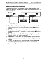
Page 62: ...he display will switch between Hi and the reading 2 Press Up arrow Max again to display the minimum reading since the last reset power up The display will switch between Lo and the reading 3 Press Ent...

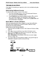
Page 63: ...o Factory Defaults When the parameters have been changed in a way that is difficult to determine what is happening it might be better to start the setup process from the factory defaults Instructions...

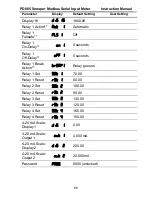
Page 64: ...f the Master mode settings have their default values loaded Model ______________ S N _______________ Date _________ Parameter Display Default Setting User Setting Mode nmode Master Function Code FunCo...

Page 65: ...dis 6 600 00 Input 7 inp 7 700 00 Display 7 dis 7 700 00 Input 8 inp 8 800 00 Display 8 dis 8 800 00 Input 9 inp 9 900 00 Display 9 dis 9 900 00 Input 10 inp 10 1000 00 Display 10 dis 10 1000 00 Inpu...

Page 66: ...off 1 0 seconds Relay 1 Break Action break1 Relay goes on Relay 1 Set Set 1 70 00 Relay 1 Reset RSt 1 60 00 Relay 2 Set Set 2 100 00 Relay 2 Reset RSt 2 90 00 Relay 3 Set Set 3 130 00 Relay 3 Reset R...

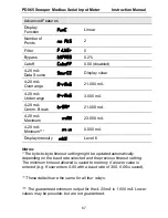
Page 67: ...000 mA 4 20 mA Maximum nmax 23 000 mA 4 20 mA Minimum nmin 0 000 mA Display intensity inty Level 6 Notes The byte to byte timeout setting might be updated automatically depending on the baud rate sel...

Page 68: ...umber 2 Lo and a number Press Menu to exit Max Min display readings Display flashes 199999 The data is less than the Input 1 value Use a lower value for Input 1 Display flashes 999999 The data is grea...

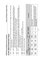
Page 69: ...um allowed Communications Break value Display Value 1 Display Value 2 Output 1 Output 2 Data mA bits and gain offset calibration factors 40401 40464 Input and Display values for 2 16 point scaling 491...

Page 70: ...elays 1 In Alarm 1 relay energized Bits 03 04 06 Read alarm status and energized non energized status of relays Alarms are read only the upper byte is ignored for writes Writing to a relay is only pos...

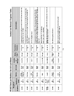
Page 71: ...iting to it has no effect 40013 12 000C Display Decimal Point Read Write 0 to 5 Integer 03 04 06 16 See Bit Assignment Table 1 40014 13 000D Transfer Function Read Write 0 to 2 Integer 03 04 06 16 See...

Page 72: ...he brightest level 40022 21 0015 Bypass Read Write 2 to 999 Integer 03 04 06 16 Corresponds to 0 2 to 99 9 If the input steps greater than the bypass value it will be displayed immediately with no fil...

Page 73: ...to 199 0 to 199 Bits 4 2 1 0 Bits 6 5 Long Long Integer Integer Word bits 03 04 16 03 04 06 16 Relay 1 parameters Set and reset points represent the display value without the decimal point See Bit As...

Page 74: ...alue without the decimal point See Bit Assignment Table 4 for operating modes and bit assignments 40122 To 40128 121 122 0079 007A 123 124 007B 007C 125 007D 126 007E 127 007F Set point Reset point Tu...

Page 75: ...20mA out Maximum value allowed Read Write 0 to 23999 Integer 03 04 06 16 Corresponds to 0 000 to 23 999 mA Because of hardware variations the actual output range is designed to be at least 1 000 to 2...

Page 76: ...311 0137 4 20mA out Output 2 Read Write 0 to 23999 Integer 03 04 06 16 4 20mA output scaling mA output at Display Value 2 Corresponds to 0 000 to 23 999 mA 40313 312 0138 4 20mA out Data in mA or Data...

Page 77: ...31 40432 400 401 0190 0191 to 430 431 01AE 01AF Input 1 to Input 16 Read Write 199999 to 999999 Long 03 04 16 Input values for the scaling of 2 to 16 data points Number of points set in Register 40015...

Page 78: ...d Only Not applicable ASCII charact ers 03 04 8 characters indicating the firmware version number 49109 To 49116 9108 9115 2394 239B Mfg Serial Number Read Only Not applicable ASCII charact ers 03 04...

Page 79: ...xample if the range is 1 99 to 1 99 and the value sent is 3 21 the value used is 1 99 or if 4 00 is sent the value used will be 1 99 Exceptions are noted in the comments Note 3 Data Types Data format...

Page 80: ...ad of the Lock register will return 0x0000 if the meter is unlocked otherwise it will return 0xFFFF to indicate a locked meter To unlock the correct lock number must be written which will then clear t...

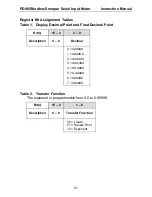
Page 81: ...imal Point and Float Decimal Point Bit s 15 3 2 0 Description 0 0 Decimal 0 dddddd 1 ddddd d 2 dddd dd 3 ddd ddd 4 dd dddd 5 d ddddd 6 dddddd 7 dddddd Table 2 Transfer Function The exponent is program...

Page 82: ...232 or RS422 1 RS485 0 None 1 Odd 2 Even 3 Even 0 300 1 600 2 1200 3 2400 4 4800 5 9600 6 19200 7 9600 Table 4 Relay Configuration 40107 114 121 128 When a relay has been disabled it can be directly c...

Page 83: ...DAC is updated when the Display value is updated The actual 4 20 mA range is limited due to component tolerances but is guaranteed by design to be at least from 1 000 to 23 000 mA Bit s 15 3 2 0 Desc...

Page 84: ...ntact Precision Digital For Technical Support Call 800 610 5239 or 508 655 7300 Fax 508 655 8990 Email support predig com For Sales Support or to place an order Call 800 343 1001 or 508 655 7300 Fax 5...

Reviews: