28
PM-236 v4 -207.indd
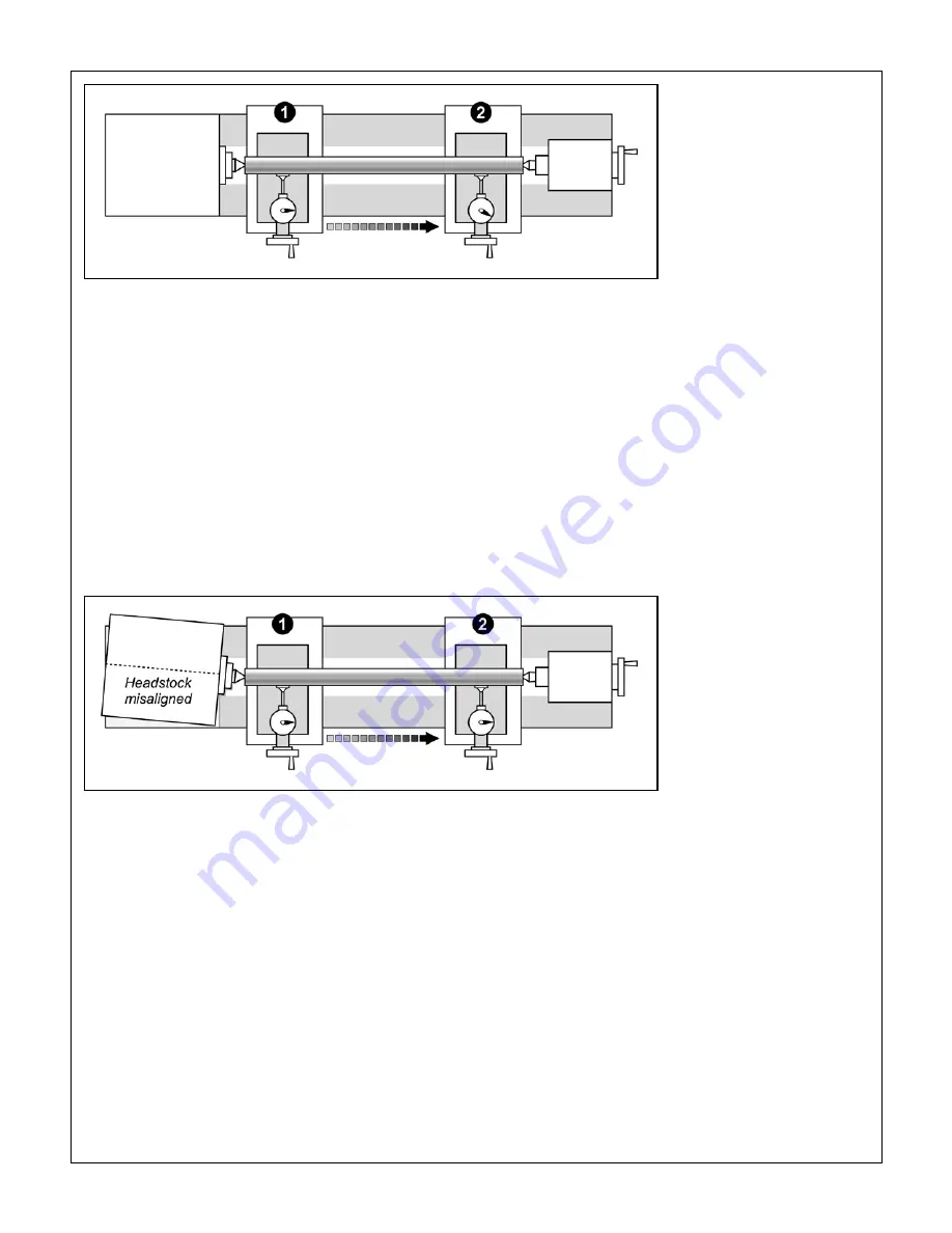
Figure C
Drill rod between
centers
Figure D
Misalignment of the
headstock has no effect on
center turning
Starting at location (), note which way the pointer rotates when the cross slide is
moved inward. In this setup the pointer is assumed to turn clockwise as the cross
slide moves in.
Pre-load the indicator by a few thousandths, then traverse the carriage from end
to end. In a perfect the setup the pointer will not move at all.
If the pointer turns clockwise as you go toward the tailstock, as Figure C, the tailstock
is biased to the front. This will cause the lathe to cut a tapered workpiece with the
larger diameter at the headstock end. Correct this by a series of
very small
adjust-
ments to the tailstock offset.
Another important question has to do with headstock/spindle alignment relative to
the lathe bed. For turning
between centers
this doesn't matter at all; the headstock
can be wildly out of square, Figure D, but the lathe will still machine parallel if the
centers have been aligned as previously described.
7.
8.
When headstock alignment really matters
Headstock alignment may not matter for center turning,
but it's critical when the workpiece is held in a chuck or
a collet — often about 90% of the workload in a typical
model shop. Assuming no appreciable deflection of the
workpiece (too thin, too far from the chuck), taper prob-
lems in a chuck/collet setup are due to misalignment of
the spindle axis relative to the lathe bed. This is usually
correctable by re-aligning the headstock.
Misalignment of the spindle by even the smallest frac-
tion of a degree causes a very measurable taper, even
over short lengths of material. For example, a misalign-
ment as small as
one hundredth of a degree
will give
a taper of 0.00” in 3 inches. If the headstock is (say) 0
inches long, this would be corrected by tapping one end
of the headstock forward or back by as little as 0.002”,
a tiny amount even if jacking screws are provided. What
this amounts to is that headstock adjustment is a
highly
sensitive, iterative procedure
that should not be at-
tempted casually. What follows is a general outline. Spe-
cific instructions for the PM-236 follow this section.
HEADSTOCK ALIGNMENT METHODS
Method 1
Make a series of "cut-and-try" passes on scrap mate-
rial. If the workpiece is thinner at the tailstock end, the
headstock needs to be pivoted away from the tool, and
vice versa.
Method 2
This uses the test rod described for center-to-center
alignment (3/4 or inch diameter ground drill rod).


