24
Copyright © 2021 Quality Machine Tools, LLC
PM-1340GT v8 2021-04
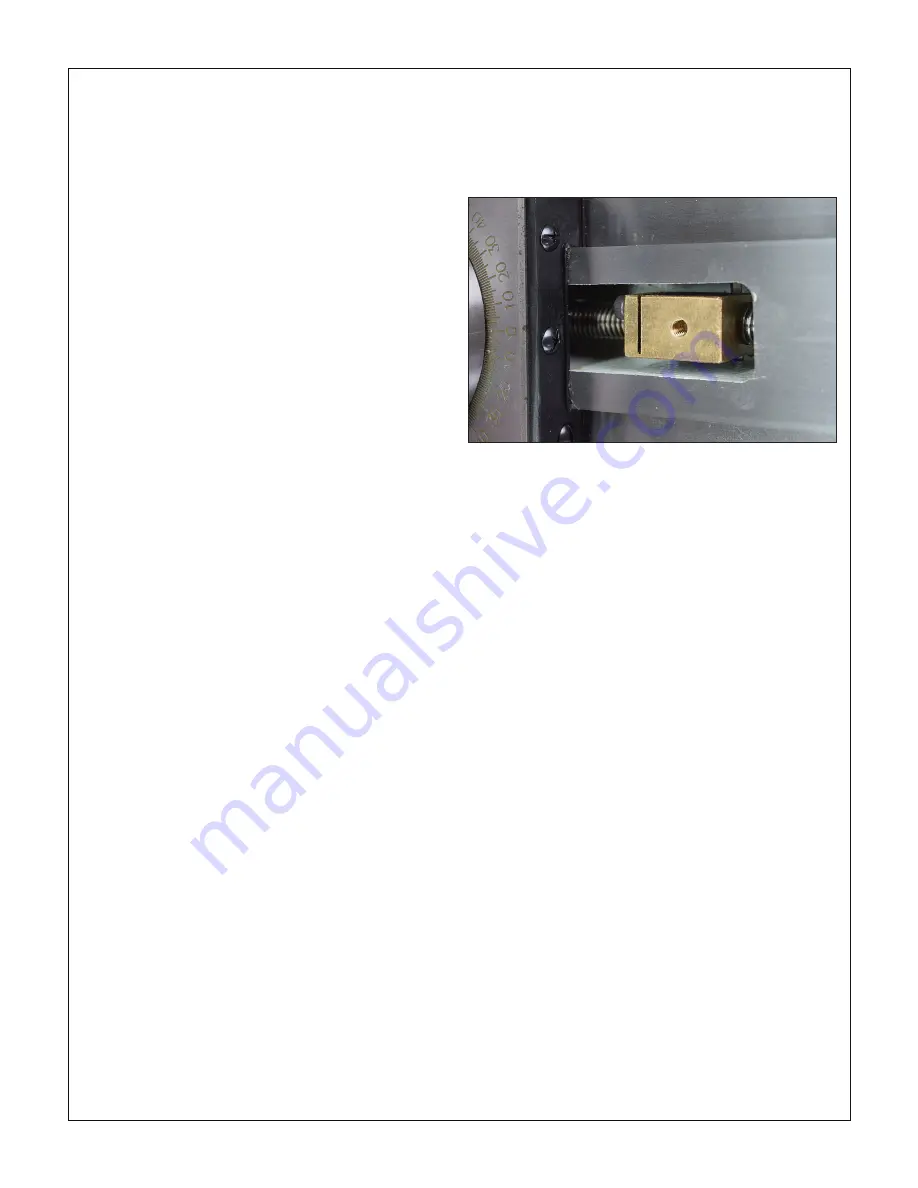
Figure 3-29
Cross slide leadscrew nut
turning operations — simply remove the draw plate and recon-
nect the cross slide leadscrew. (Alternatively, leave the attach
-
ment intact, with the taper guide bar set for zero degrees; in
this case use the compound for tool control.)
Referring to Figure 3-28, install the taper turning attach-
ment as follows:
1.
Remove the socket head cap screw securing the cross
slide leadscrew nut to the cross slide body, Figure 3-29.
Push/pull the cross slide a few times front to back to be
sure the no-longer-captive nut allows free movement
throughout the range called for by the taper attachment.
2.
Make certain that the cross slide gib is properly adjusted
for smooth motion without side play.
3. Because the cross slide leadscrew is inoperative, the
compound is typically used to infeed the cutting tool. If the
infeed needs to be precisely controlled, set the compound
to 90 degrees.
4.
Install the taper attachment base on the lathe carriage (4
socket head screws).
5.
Install the draw plate on the cross slide, with the two
round-head socket screws (1) snug but not tight.
6.
Check the underside of the draw plate where it meets the
center post. It should touch the post with zero gap. Make
minor adjustments to the relative height of the attachment
base (4 screws), or pack with washers as necessary. (mis
-
alignment here can impose a vertical load on the cross
slide.)
7.
Loosen the tie rod clamp screws, also the set screw se-
curing cam (5). Screw the tie rod into the slide.
8. Set the clamp assembly in the desired location on the rear
track of the lathe bed. Rotate the cam to raise or lower the
tie rod socket (4) as necessary.
9. Tighten the tie rod and clamp screws, then re-check the
center post/draw plate interface.
10. Set the draw plate as desired for the turning operation.
Tighten screws (1) and (2). Tighten the cam set screw.
11.
Loosen screws (3), set the desired taper angle, see be
-
low. Re-tighten the screws.
12. Use the carriage handwheel to run the lathe carriage
back and forth a few times, checking for smooth, consis
-
tent functioning of both cross slide and follower carriage.
There should be no change in load from one end of the
taper to the other.
13.
With the workpiece installed engage carriage power feed
to cut the taper.
Setting the taper angle
No matter what method you use to set the taper angle, bear in
mind that all dial indicating should be done
in one direction
only
to eliminate backlash.
1. If you are using only the angle scale on the attachment
to set a taper, the taper guide bar needs first to be ze
-
roed relative to the lathe bed. Do this using a ground bar
between centers or in a chuck, see above, with a mag
-
netic-based dial indicator positioned on the cross slide so
that its probe runs on the bar. Adjust the taper angle for
zero deflection along the length of the bar.
2. To cut a matching taper, use the same setup to indicate
the reference item, either between centers or held in the
chuck. Aim for zero deflection as the probe traverses the
taper. This calls for patience — expect several iterations
to achieve this. Be sure the indicator probe is at center
height.


