background image

17

PM-1440BV v3 2020-10

Copyright © 2020 Quality Machine Tools, LLC

CHUCKS & FACEPLATE

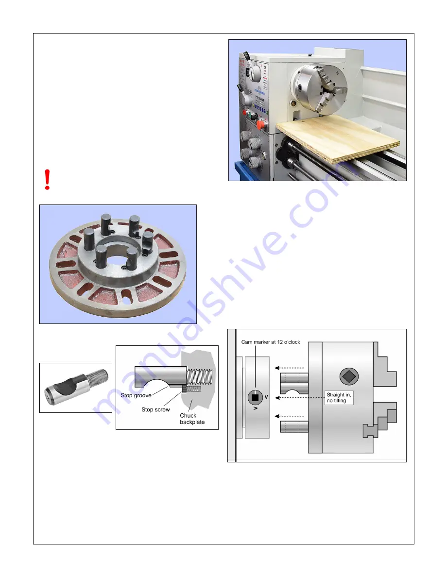
The spindle nose on the PM-1440BV accepts D1-5 Camlock 

chucks, faceplates and other work holding devices.

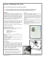
A D1-5 chuck or faceplate is held by six threaded studs, each 

with a D-shape crosscut to engage a corresponding cam in the 

spindle nose, Figures 3-21, 3-22. The function of the cams is 

to pull the chuck backplate inward to locate its internal taper 

firmly on the spindle nose.

Alongside  each  stud  is  a  stop  screw,  the  head  of  which  fits 

closely in a groove at the threaded end of the stud. The func-

tion of the stop screw is not to clamp the stud in place, but 

instead to prevent it from being unscrewed when the chuck is 

out on the bench.


TO INSTALL A CHUCK

Disconnect the 220V supply from the lathe!

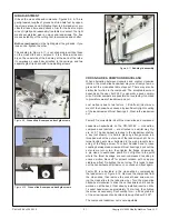
D1-5 chucks and faceplates are heavy, some more than 30 

lb. They will cause serious damage if allowed to fall. Even if a 

chuck is light enough to be supported by one hand, the lathe 

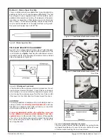
bed should be protected by a wood scrap, as Figure 3-23. 

Some users add packing pieces, even custom-made cradles, 

to assist “straight line” installation and removal.

All stop screws must be present & fully tightened! 

Camlock action can jam any stud lacking a stop 

screw  — a serious problem.

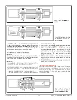
Figure 3-21  

D1-5 faceplate

Figure 3-22  

Camlock stud

Before installing make certain that the mating surfaces of the 

chuck/faceplate and spindle are 

free of grit and chips

.

The cams on the spindle are turned with a square-tip wrench 

similar to the chuck key (may be same tool in some cases).

Recommended procedure:

1.  Select the high speed range 

H

 to allow easier hand rotation 

of the spindle.

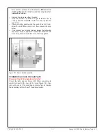
2.  Turn the spindle by hand, checking that all six cam markers 

are at 12 o’clock.

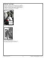
3.  While 

supporting its full weight

, install the chuck without 

tilting, see Figure 3-24, then gently turn each of the cams 

clockwise

 — snug, firm, but not locked in this first pass.

Figure 3-23  

Protect the lathe bed

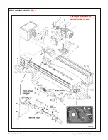
4.  Check that each of the cam markers lies between 3 and 

6 o’clock, between the two Vees stamped on the spindle, 

Figure 3-25.

5.  If any cam marker is 

not

  within  the  Vees,  first  be  sure 

that there is 

no gap

 between chuck backplate and spin-

dle flange. Also, remove the chuck to inspect the studs — 

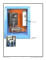
Figure 3-24  

Installing a Camlock chuck

Summary of Contents for PM-1440BV

Page 1: ...ore spindle 2 inch clearance D1 5 camlock spindle mount 40 in between centers 14 in swing over bed 18 3 4 in over gap Multi speed gearbox for full range screw cutting TPI mm pitch Bidirectional power...

Page 2: ...he information given here with little or no impact on functionality Please email us if you have questions about any aspect of the manual or your machine see our website www precisionmatthews com for s...

Page 3: ...ly the 3 shafts at the front Use at least 2 by spreaders Figure 1 1 Lifting with slings Spreader under the bed keeps slings chains clear of feed shafts etc Before lifting remove the chuck if installed...

Page 4: ...l on the ground surface of the cross slide as the carriage is traversed from end to end See also Aligning the Lathe in Section 4 FOOTBRAKE INTERLOCK The lathe will not run if the footbrake switch fail...

Page 5: ...happen the E stop function is defective and needs attention 14 Reset twist the E Stop button to restore power 15 Check that the footbrake stops the motor 16 Return the motor control lever to OFF mid t...

Page 6: ...deal for through spindle work such as gunsmithing Long service life is assured by high precision taper roller spindle bearings together with hardened and ground bed ways shafts and headstock gears All...

Page 7: ...Compound top slide travel 3 3 4 in Drive system VFD drive with 2 speed gearbox Low range rpm 40 to 400 High range rpm 220 to 1800 Carriage drive thread cutting Leadscrew 8 tpi Inch threads Choice of 3...

Page 8: ...an be hazardous Be sure the work area is properly lit Never leave chuck keys wrenches or other loose tools on the machine Be sure the workpiece toolholder s and machine ways are secure before commenci...

Page 9: ...nd that the Motor Control Lever on the apron is mid travel off Figure 3 2 Check that the drive train L or H range is properly engaged then operate the Motor Control Lever to run the spin dle in the de...

Page 10: ...Figure 3 5 Figure 3 5 Power feed rates inches per spindle rev For any given change gear and gearbox selection sad dle motion is approximately 3 times cross slide motion T S R U T S R U A D 0 0548 0 05...

Page 11: ...Figure 3 6 Saddle stop representative Figure 3 7 Feedshaft clutch THREAD CUTTING External change gears The large gears in Figures 3 3 and 3 8 are transposing gears 120T and 127T They allow a standard...

Page 12: ...ate the gears Gear shifters R 4 U 4 S 3 T 4 U 1 R 3 T 1 U 3 U 1 Upper gear 56 60 60 30 60 60 30 60 42 Lower gear 60 60 60 60 60 60 60 60 63 A D 7 0 6 0 5 0 4 5 4 0 B D 3 5 3 0 2 5 2 25 2 0 1 8 1 6 A C...

Page 13: ...ing dial If the TPI number is divisible by 2 re engagement can be done at any line on the threading dial For all other TPI numbers every engagement including the first must at the point where a specif...

Page 14: ...rews on either side Figure 3 15 To move the tailstock to the back for instance the screw on the lever side would be unscrewed then the opposing set screw would be screwed in to move the upper assembly...

Page 15: ...ct The follower rest Figure 3 18 is secured to the saddle with two 8 mm socket head screws Adjust the follower fingers as described for the steady rest Figure 3 17 Steady rest representative Figure 3...

Page 16: ...eir potential for corrosion and other undesirable effects on the lathe and the coolant pump If you use water miscible cutting fluid bear in mind that the ratio of product to water is important too muc...

Page 17: ...users add packing pieces even custom made cradles to assist straight line installation and removal All stop screws must be present fully tightened Camlock action can jam any stud lacking a stop screw...

Page 18: ...second Vee 6 o clock screw the stud IN one more turn then replace the stop screw If the markers are correctly aligned repeat the tightening sequence as step 3 light force Repeat the sequence two more...

Page 19: ...8 such as Mobil DTE Heavy Medium circu lating oil Approximate quantities required Headstock 4 quarts Saddle feed gearbox 2 quarts Apron 1 quart Ball oilers ISO 68 way oil such as Mobil Vactra No 2 or...

Page 20: ...c tube in serted into the fill hole Add oil to the halfway mark on the sight glass on the front panel of the gearbox about 2 qts APRON GEARBOX DRAIN REFILL Remove the fill plug Figure 4 5 Remove the d...

Page 21: ...motion is due to two factors 1 End float in out move ment of the handwheel caused by insufficiently tight coupling of the leadscrew and thrust bearings 2 Wear in the leadscrew nut Factor 1 is correct...

Page 22: ...on 5 electrical schematic SPLIT NUT ADJUSTMENT In thread cutting operations if the split nut becomes exces sively loose appreciable side to side movement this may be corrected by adjusting the gib at...

Page 23: ...on If adjustment is necessary loosen the three hex head bolts se curing the motor frame to the headstock Figure 4 17 Do not loosen the bolts attaching the motor to its frame Firm finger pressure here...

Page 24: ...just for minimum TIR then drill the other end 5 Set the drill rod snugly between centers as Figure C Lock the tailstock 6 Set a dial indicator on the cross slide to eliminate vertical error use a flat...

Page 25: ...t the chuck for minimum runout at position 1 2 Check the runout at 2 Pointer movement when traversing is not a concern at this stage 3 If the drill rod is perfectly aligned with the spindle axis there...

Page 26: ...Figure A3 Misaligned headstock In this illustration the workpiece diameter increases as the cut ting tool moves toward the chuck Correct this by screwing in A a fraction of a turn to rotate the headst...

Page 27: ...ality Machine Tools LLC Section 5 PARTS Upper electrical box KM3 KA2 KA1 and KA0 are all low voltage 24Vac relays contactors Swap these wires to change motor direc tion motor control lever down spindl...

Page 28: ...28 PM 1440BV v3 2020 10 Copyright 2020 Quality Machine Tools LLC Lower electrical box VFD Brake resistor...

Page 29: ...29 PM 1440BV v3 2020 10 Copyright 2020 Quality Machine Tools LLC...

Page 30: ...30 PM 1440BV v3 2020 10 Copyright 2020 Quality Machine Tools LLC STAND COMPONENTS Fig 1 There may be detail differences between this representative drawing and the machine as supplied...

Page 31: ...y Z3044 21 Coolant pump Z3045 22 Hose connector Z3046 23 Coolant container Z3047 24 Socket head screw M10 30 Z3048 25 Hexagon nut M10 Z3049 Ref Description Part 26 Socket head screw M6 10 Z3050 27 LH...

Page 32: ...32 PM 1440BV v3 2020 10 Copyright 2020 Quality Machine Tools LLC BED COMPONENTS Fig 2 There may be detail differences between this representative drawing and the machine as supplied...

Page 33: ...ew Z3100 28 Roll pin 5 20 Z3101 29 Socket head screw M6 16 Z3102 30 Short rack Z3103 31 Long rack Z3104 32 Key 4 50 Z3105 33 Bushing Z3106 34 Screw M8 8 Z3107 35 Spring 6 1 15 Z3108 Ref Description Pa...

Page 34: ...Washer 10 Z3147 3 Retaining ring 35 Z3148 4 127T 120T gear pair Z3149 5 Thrust bearing 6003 Z Z3150 6 Shouldered bushing Z3151 7 Gear quadrant Z3152 8 Nut M12 Z3153 9 T bolt Z3154 Ref Description Part...

Page 35: ...83 Steel ball 6 Z3176 84 Spring 6 1 10 Z3177 85 Screw M8 8 Z3178 86 Indicator Z3179 87 Screw M4 8 Z3180 88 Roll pin 4 50 Z3181 89 Handle Z3182 90 Screw M6 8 Z3183 91 Spring 5 1 25 Z3184 92 Steel ball...

Page 36: ...36 PM 1440BV v3 2020 10 Copyright 2020 Quality Machine Tools LLC HEADSTOCK COMPONENTS Fig 5 There may be detail differences between this representative drawing and the machine as supplied...

Page 37: ...ead screw M6 25 Z3226 28 Socket head screw M4 12 Z3227 29 Cover plate Z3228 30 Gasket Z3229 31 Ball bearing 6204 Z3230 32 Washer Z3231 33 Gear Z3232 34 Gear Z3233 Ref Description Part 35 Gear Z3234 36...

Page 38: ...2 79 Steel ball 6 Z3273 80 Spring 6 1 25 Z3274 81 Screw M8 8 Z3275 82 Washer 6 Z3276 83 Socket head screw M6 12 Z3277 Ref Description Part 84 Indicator plate Z3278 85 Screw M4 6 Z3279 86 Front panel Z...

Page 39: ...39 PM 1440BV v3 2020 10 Copyright 2020 Quality Machine Tools LLC FEED GEARBOX CONTROLS Fig 6 There may be detail differences between this representative drawing and the machine as supplied...

Page 40: ...Shaft Z3313 26 Cover plate Z3314 27 Gasket Z3315 28 Key 4 55 Z3316 29 Shaft Z3317 30 Key 4 80 Z3318 31 Shaft Z3319 32 Key 4 18 Z3320 33 Gasket Z3321 34 End cover Z3322 35 Cover plate Z3323 36 Gasket Z...

Page 41: ...41 PM 1440BV v3 2020 10 Copyright 2020 Quality Machine Tools LLC APRON Fig 8 There may be detail differences between this representative drawing and the machine as supplied...

Page 42: ...dicator body Z3393 39 Washer 8 Z3394 40 Nut M8 50 Z3395 45 Rivet 2 5 Z3396 48 Drain plug Z3397 49 Split nut indicator Z3398 50 Sight glass A20 Z3399 Ref Description Part 51 Roll pin 5 35 Z3400 52 Spri...

Page 43: ...43 PM 1440BV v3 2020 10 Copyright 2020 Quality Machine Tools LLC CROSS SLIDE SADDLE Fig 9 There may be detail differences between this representative drawing and the machine as supplied...

Page 44: ...t head screw M6 16 Z3458 20 Socket head screw M10 30 Z3459 21 Taper pin 6 45 Z3460 22 Rubber wiper LH Z3461 23 Socket head screw M10 45 Z3462 24 Saddle casting Z3463 25 Gib screw Z3464 Ref Description...

Page 45: ...ol post Z3500 13 Pillar Z3501 14 Tee plate Z3502 15 Leadscrew Z3503 16 Leadscrew nut Z3504 17 Key 4 14 Z3505 18 Support flange Z3506 19 Skt head screw M6 16 Z3507 20 Ball bearing 51103 Z3508 21 Gradua...

Page 46: ...5 Quill clamp block brass Z3535 16 Stop pin Z3536 17 Quill clamp shaft Z3537 18 Quill clamp handle Z3538 19 Knob M8x40 Z3539 20 Screw M12 45 Z3540 21 Washer 12 Z3541 22 Adjusting screw Z3542 23 Lock s...

Page 47: ...Adjusting screw Z3561 5 Plunger Z3562 6 Cone point Z3563 7 Thumb nut Z3564 8 Hinge casting Z3565 9 Nut M6 Z3566 10 Screw M6X18 Z3567 11 Screw M6X30 Z3568 12 Hinge clamp screw Z3569 13 Pin 5X24 Z3570 1...

Reviews: