11
Copyright © October 2017 Quality Machine Tools, LLC
PM-1440E-LB 11-13-17 V1
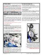
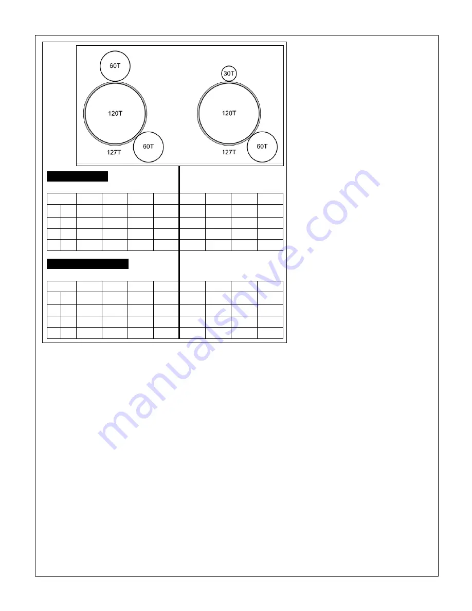
Figure 3-6
Power feed rates (inches per spindle rev)
For any given selection, saddle motion is approximately 3 times cross-slide motion.
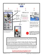
FEEDSHAFT CLUTCH
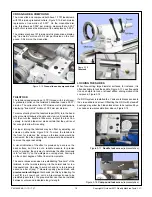
The clutch shown in Figure 3-7 disengages the power feed if
the saddle or cross-slide hits an obstruction when power feed-
ing, thus minimizing the potential for damage. This could be
the result of either an accidental event, or deliberately stopping
the saddle at a precise location set by the saddle stop, Figure
3-8.
T
S
R
V
T
S
R
V
A D
0.0187 0.0175 0.0140 0.0112 0.0094 0.0087 0.0070
0.0056
B D
0.0094 0.0087 0.0070
0.0056
0.0047 0.0044 0.0035 0.0028
A C
0.0047 0.0044 0.0035 0.0028 0.0024 0.0022 0.0017 0.0014
B C
0.0024 0.0022 0.0017 0.0014 0.0012 0.0011 0.0009 0.0007
T
S
R
V
T
S
R
V
A D
0.0548 0.0512 0.0411 0.0328 0.0274
0.0256
0.0205
0.0164
B D
0.0274
0.0256
0.0205
0.0164
0.0137 0.0128 0.0102 0.0082
A C
0.0137 0.0128 0.0102 0.0082
0.0069 0.0064
0.0051 0.0041
B C
0.0069 0.0064
0.0051 0.0041 0.0034 0.0031 0.0025 0.0020
SADDLE FEED
Inches/spindle revolution
CROSS-SLIDE FEED
Inches/spindle revolution
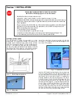
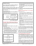
EXTERNAL GEAR SWAPPING
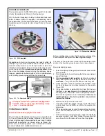
The 120T and 127T gears in Figures 3-5 are called
transpos-
ing gears
. They allow a standard-thread leadscrew — in this
case 8TPI — to cut metric threads.
For U.S. (TPI) thread cut-
ting there is no transposing requirement
— the 127T gear
acts only as an idler, transferring drive directly from the head-
stock to the gearbox.
Any change to the drive train typically calls for one or both
of the upper and lower gears to be exchanged for a larger or
smaller gear. This will require the transposing gears to be re-
positioned. The procedure for this is:
1.
Remove the hex nuts from the upper and lower gear shafts.
2. Remove the upper and lower gears, washers and keys.
3.
While holding the gear support casting (quadrant) with one
hand, loosen its anchor nut and clamp screw. Allow the
casting to swing downward.
4.
Loosen the hex nut securing the transposing gear axle to
the support casting.
5. Install the lower gear.
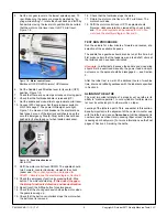
6.
For
power feeding
or
U.S. (TPI) thread cutting
, bring
the larger transposing gear (127T) into mesh with the low
-
External
gears
er gear, running a scrap of printer paper (about 0.004")
trapped between the two to set them at the correct sepa-
ration. For
metric thread cutting
, mesh the smaller trans-
posing gear (120T) with the lower gear, Figure 3-9.
7. Tighten the transposing gears in position, then remove the
paper scrap. Check again for working clearance between
the gears.
8. Install the upper gear.
9. Swing the gear support casting upward to mesh the 127T
gear with the upper gear, again using a paper scrap for
separation.
10. Tighten the gear support casting.
11. Lubricate the gears.


