24
PM-1440E-LB 11-13-17 V1
Copyright © October 2017 Quality Machine Tools, LLC
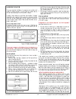
DRIVE TRAIN
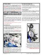
Double-groove pulleys co
nnect the motor to the gearbox. Belt
tension will not usually require attention. If necessary, loosen
the three hex head bolts securing the motor, Figure 4-17. Ad
-
just the motor to re-tension. Make certain the motor is properly
aligned, then re-tighten the bolts.
Figure 4-17
Vee belts
Firm finger
pressure here
should deflect
the Vee belt
about 1/4"
Figure 4-18
Motor attachment bolts
(representative)
Do not loosen the bolts securing the motor to this casting!
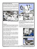
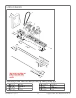
TAILSTOCK BED CLAMP
The angular position of the bed clamp lever is adjustable. Slide
the tailstock toward the headstock to expose the threaded
stop screw at the right hand end of the bed. Remove the stop
screw, then
very carefully slide
the tailstock to the right, just
far enough to allow access to the hex nut below the tailstock
bed plate. Tighten the nut as necessary.
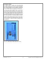
Figure 4-15
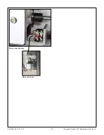
Footbrake microswitch
(LH stand cabinet)
Figure 4-16
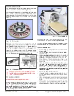
Brake assembly
(representative)
BRAKE ASSEMBLY
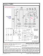
The treadle-operated brake does two things: 1. It disconnects
power from the motor, Figure 4-15, and; 2. It expands brake
shoes against the hollowed-out inboard face of the driven pul-
ley.
Inspection of the brake assembly, Figure 4-16, may be a
two-person job, Person A to lock the driven pulley while Person
B removes the socket head screw securing the driven pulley.
The inboard face of the driven pulley (the brake drum) should
show no gouging or irregularities. Minor damage may be cor-
rectable by skimming; otherwise consider replacing the item.
The brake pads should be clean, evenly worn, showing no sign
of oil. Minimum pad thickness is 4.5 mm, about 0.18". If nec-
essary replace the pads by separating them — extending the
springs — then lifting them clear of the retaining studs.

