background image

Version: A.00 

AgGuide V6 Operation Manual


Page 24


Speed: 

This indicates the current vehicle speed as provided by the GPS. 

Swath: 

This indicates the current swath or pass with respect to the originating runline. Swaths to the right of the orginal 
runline will be displayed as a  positive number, swaths to the left will be displayed as a negative number.  

Applied: 

This indicates the total applied area in the current job. Applied area is  controlled by the Run/ Hold function on 
the main screen.  


 Guidance Display 

The guidance display includes a Cross Track error  indicator and a visual guidance display.  


xTrack: 

The xTrack indicator  displays the Cross Track Error (XTE) which is the distance the vehicle is away from the 
selected runline. A positive value indicates the vehicle is to the right of the runline, negative values indicate the 
vehicle is to the left.  

Visual Guidance Display: 

When operating in Visual Guidance mode (i.e non-Autosteer) a colored lightbar displays at the top of the map. 

The colored arrows indicate which way the vehicle must be turned to return to the line. Visibility of the  Lightbar 
can be configured in the Vehicle Settings page.  


 Main Menu  

Cross Track Indicator


Visual Guidance Display


Summary of Contents for AgGuideV6

Page 1: ...GPS GUIDANCE AUTOSTEER LAND LEVELLING SPRAYING VARIABLE RATE CONTROL Operation Manual...

Page 2: ...nd warnings are provided in this manual and or on the supplied equipment Failure to heed these warnings may result in equipment damage serious injury or death The warnings in this manual and or on the...

Page 3: ...mation This symbol will be used critical information when failure to follow the instructions may cause injury or death Important Information This symbol will be used when failure to follow the instruc...

Page 4: ...Signals 10 Correction using Satellite or long distance land based stations 11 Local base stations 11 Base Stations local 12 Base Stations mobile 13 Community Base Stations 14 COMPONENTS OF THE SYSTEM...

Page 5: ...ient 33 Importing a Client from AgGuide V4 33 Deleting a Client 33 Managing Farm Data 34 Open the Farms Page 35 Adding a new Farm 35 Renaming a Farm 35 Deleting a Farm 35 Managing Field Data 36 Openin...

Page 6: ...allel 54 Selecting A Direction Recording 54 Recording A Direction 55 Selecting Contour Recording 55 Recording Contour Runline 55 Selecting Pivot Recording 55 Recording Pivot Runline 55 Advanced Operat...

Page 7: ...3 Creating a Vehicle 73 Vehicle Dimensions 73 Vehicle GPS configuration 73 Steering System Configuration 73 WAS Calibration 73 Nav Module Configuration 73 Tuning 73 Troubleshooting 73 IMPLEMENT CONFIG...

Page 8: ...Version A 00 AgGuide V6 Operation Manual Page 8 AGCO Fendt Vario 74 CLAAS Lexion 770 74 CNH Austoft Tracked Hydraulic 74 LEVEL GUIDE 74...

Page 9: ...ide V6 can be used to assist in steering of the vehicle when used in conjunction with a suitable kit enabling secondary control over the steering Once this option has been enabled GPS guidance as abov...

Page 10: ...follows Sub meter defined as accuracies less than a meter but greater than 15cm 10cm usually defined as accuracies between 10 and 15 cm this includes suppliers such as OmniSTAR HP Terrastar D 2cm also...

Page 11: ...thin Australia and NZ Local base stations Using a local base station enables high accuracy correction without the need for annual subscription This must be offset by the capital cost of a base station...

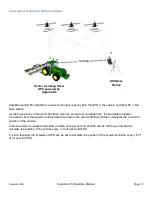
Page 12: ...al as high as possible will get best possible performance 2 The GPS antenna must be mounted so that it has a clear 360 view of the horizon any obstacles may create performance problems e g black spots...

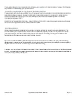
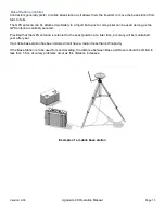
Page 13: ...n be used as long as the GPS antenna is suitably secured Provided that the GPS antenna is returned to the exact position at a later time accuracy will be maintained year after year If a mobile base st...

Page 14: ...ns are collaborative fixed GPS base stations that are accessed by a group of farmers that work their properties in the same area They are typically set up by a co operative of private farmers to maxim...

Page 15: ...iation correction from this position is transmitted via radio to the vehicle GPS which then calculates the corrected position of the vehicle Correction data is usually transmitted via radio once per s...

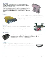
Page 16: ...nd manages all of your customized farm specific data including farms fields and boundaries It calculates and translates the GPS positioning data allowing you to enjoy the benefits of high accuracy ste...

Page 17: ...uired Wheel Angle Sensor OR The Wheel Angle sensor is an integral part of the auto steer system and will need to be both fitted and commissioned correctly for the system to operate Its prime job is to...

Page 18: ...day The UniPOD can be pre programmed for Spray Control Seeder Control Spreader control Steering levelling control Hydraulics For Hydraulic Steering and some implement control applications additional H...

Page 19: ...Guide Selecting a Vehicle Selecting an Implement Selecting a Job Selecting Fields Selecting Runlines Fields can be filtered by Client and Farm selection on the Fields tab menu Only Fields associated w...

Page 20: ...approach angle the Auotsteer button will be red and Autosteer cannot be activated When the system is Ready To Engage RTE the Autosteer button will change to orange and Autosteer can be activated Sele...

Page 21: ...iPod Unlock Code Visual Guidance Required Required Auto Steer Required Required Required Sprayer Control Required Required Optional Required Seeder Control Required Required Optional Required Implemen...

Page 22: ...use select the View Terms button This will display a new window with the option to accept or decline the terms and conditions If the terms and conditions are declined the application will exit This bu...

Page 23: ...laces Latency This indicates the number of seconds since a correction signal has been received from the base When no correction is available the indicator will display 0 North direction Indicator Info...

Page 24: ...lay The guidance display includes a Cross Track error indicator and a visual guidance display xTrack The xTrack indicator displays the Cross Track Error XTE which is the distance the vehicle is away f...

Page 25: ...Radio configuration and configure Base Stations Please refer to the GPS Configuration section for more detailed instructions Vehicle Menu The vehicle menu allows you to view edit and select vehicle c...

Page 26: ...verview Map provides the map screen in a smaller view This is useful when running other applications such as Variable Rate or Levelling where the implement control is displayed in the main window Unit...

Page 27: ...rd an Interior or Exterior boundary in a field Selecting this button will toggle visibility of the Boundary recording fly out menu The flyout menu will remain visible on screen when the Main Menu is c...

Page 28: ...configures Base Selection in the GPS Receiver COM The COM Button displays the COM Menu for configuration of data communications for system components This includes CORS Terminal COM ports CAN Bus conf...

Page 29: ...Control Mode and implement geometry Steering The Steering button allows you to adjust implement steering gain and steering settings Bins Tanks The Bins Tanks button allows you to configure product Bin...

Page 30: ...LevelGuide and other features File Manager The File Manager button opens the Windows file manager Log Data This button stores the last two minutes of data from the system This information can be anal...

Page 31: ...d marked features or obstacles The relationship between the entities is shown below Confirm Relationship for no Client Each Farm may contain multiple fields with each field containing multiple runline...

Page 32: ...w displays a geographical outline of the Fields associated with the selected client Back Button Closes the page and returns to the main window Any changes in selection will persist Client List Display...

Page 33: ...ient When user selects Add New the virtual keyboard will be displayed When user selects Rename the virtual keyboard will be displayed Delete Client When user selects Delete a confirmation window will...

Page 34: ...lays a geographical outline of the Fields associated with the selected client Back Button Closes the page and returns to the main window Any changes in selection will persist Farms List Displays a lis...

Page 35: ...rtual keyboard will be displayed When user selects Rename the virtual keyboard will be displayed When user selects Delete a confirmation window will be displayed Farm Record will be deleted Cancels de...

Page 36: ...e Fields associated with the selected Field Back Button Closes the page and returns to the main window Any changes in selection will persist Fields List Displays a list of all Fields associated with t...

Page 37: ...iated with the selected Client or Farm will be displayed When user selects Add New the virtual keyboard will be displayed When user selects Rename the virtual keyboard will be displayed When user sele...

Page 38: ...fine the zone by the following Importing a shape file to define a field Automatically determining zone from GPS information This will work for any user not close to or overlapping the boundary of a zo...

Page 39: ...d item up or down in the list This applies to all items in the Client Farm and Field pages Cut Button Cut will select and remove the selected item from the current list This is applicable to Farm and...

Page 40: ...ent list When user selects Duplicate the virtual keyboard will be displayed Enter new name for the Client to be copied Select Copy or Cut to place item on Clipboard Select the Farm or Field that you w...

Page 41: ...y recording the vehicle path or by a combination of both When setting points the vehicle path between the points is not recorded resulting in a straight line eliminating variations in vehicle position...

Page 42: ...ion Manual Page 42 It is possible to create multiple external boundaries in the same field It is possible to create interior exclusion zone outside of field Creating a new boundary doesn t automagical...

Page 43: ...ding point to the Left of the implement swath Center Record Point Sets the boundary recording point to the center of the implement swath Right Record Point Sets the boundary recording point to the rig...

Page 44: ...to record the curved headland area At Point 4 the boundary is once again straight and parallel to the original AB runline Engage the AB runline and select Pause At point 5 the switch from Paused to Ru...

Page 45: ...ing is running recording will continue even when the menu is not visible Select Centre left or Right recording position Close the Flyout Select Interior or Exterior boundary Type Close the Flyout Sele...

Page 46: ...Manual Page 46 Recording Field Boundary Start recording by selecting either Run Mode or Set Point Pause Recording or add additional Points Resume recording or add additional points Select Finish to c...

Page 47: ...line only present a set number of passes A headland line position is independent of the implement width ie passes recorded with a 3 m implement will remain at 3m swath if a different implement configu...

Page 48: ...ds a single point to the Headland Line This creates a line segment between the new point and the last recorded point Disable Headland Mode Button When selected headland recording will be disabled Enab...

Page 49: ...ting the Set point button This creates the starting point of the Headland line At point 2 Headland recording is switched to recording mode to record an irregular area of the headland At point 3 result...

Page 50: ...der Flyout Menu If the Headland recording is running recording will continue even when the menu is not visible Select to Enable or Disable headland recording Close the Flyout Selecting the Number of P...

Page 51: ...tain straight and curved sections Pivot A pivot Runline is a circular path used for Center Pivot irrigation fields During normal operation the system will generate Runlines based on the current positi...

Page 52: ...daptive and adptive not working Parallel Mode When operating in Parallel Mode the line is repeated and no smoothing is applied to the line Adaptive Mode When operating in Adaptive mode smoothing is ap...

Page 53: ...ne Menu Contour Recording Mode Runline Menu Pivot Recording Mode Runline Menu A Recording Mode Finish Set B Point Set A Point AB Mode A Mode Set A Point Set Heading Finish Run Mode Set Point Pause Mod...

Page 54: ...use Mode will suspend point recording On resume by either Run or set point a segment will be created from the last recorded point Set Point Button Adds a single point to the Runline This creates a lin...

Page 55: ...umeric keypad will be displayed Enter the required heading and press the Back button Start recording by selecting either Run Mode or Set Point Pause Recording or add additional Points Resume recording...

Page 56: ...Version A 00 AgGuide V6 Operation Manual Page 56 AB Finish doesn t cancel Doesn t respect minimum distance of Set B Should it be visible...

Page 57: ...tion the following can be performed A runline can be created and used for Autosteer and boundary Recording to ensure accurate boundary placement Headland Passes can be created during boundary creation...

Page 58: ...Headland or Boundary buttons from the Menu will toggle visibility of the Fly out Menus Recording Point When performing simultaneous recording of boundaries and Runlines or Headland Line the recording...

Page 59: ...ses page Changing the selected Headland will select the Headland pass in the Job and mapping Window Preview Window The preview Window shows the Field boundary and all associated Runlines and Headland...

Page 60: ...To use runline with an implement that is 10m wide the Runline width and offset need to be changed If the 3m implement original Line was recorded at 1 5 m from the boundary Blue Line the line position...

Page 61: ...ield Select the Runline from the Runline List Select Parallel Adaptive or Headland Runlines Press the Back Button to close the Runlines Page The Selected Runline will be displayed on the Mapping Windo...

Page 62: ...y be copied into the Runlines page for the selected Field Select the Runline that you want to copy or move Select the Runline that you want to edit Pressing the Settings button will show the Settings...

Page 63: ...screen Add Button Adds a new Job to the currently selected Field Delete Button Deletes the Job All Job data will be removed Rename Button Renames the Selected Job When selected a virtual keyboard wil...

Page 64: ...the required Job from the Jobs List and press the Back Button Note that Jobs will only be displayed for the currently selected Client Farm Field Select the required Field then select Back Button When...

Page 65: ...data associated with the Job Select the Job you want to copy or move from the Job List Select Copy or Cut to place item on Clipboard Cut will remove the Job from the current Field Select the destinat...

Page 66: ...pen a new window displaying Job Statistics including the following Date Time the Job was created When the Job was executed Active hours Applied hours The Driven Area The Applied Area Overlapped Area E...

Page 67: ...67 Displaying Job Statistics As and interim included Vehicle and Implement Setup pages Thes should move to Vehicle and Implement Config for final release After selecting Statistics a new window will...

Page 68: ...close the Settings page and return to the Mapping Window Any changes to vehicle setup will persist Configuration This will set the Vehicle type Options are Front Wheel Steer Rear Wheel Steer Tracked A...

Page 69: ...e Setup Page Important Information Changes to Vehicle Configuration or Vehicle measurements may have an adverse affect on System performance or accuracy These values are set during installation on the...

Page 70: ...pping Window Any changes to implement setup will persist Configuration This will set the Implement mounting configuration Rows per Implement Swath Width Mode This option selects if the implement width...

Page 71: ...Version A 00 AgGuide V6 Operation Manual Page 71 Opening the Implement Setup Page...

Page 72: ...ion Manual Page 72 WORKING WITH PLANS Overview What are plans prescription Maps levelGuide cut fill etc Prescription Map Adding Prescription Map Edit Prescription Map Using Prescription Map with Imple...

Page 73: ...ation Topcon Reciver Conf Base Station Config External GPS Nema Out for external devices 0183 NEMA 2000 VEHICLE CONFIGURATION Creating a Vehicle Vehicle Dimensions Vehicle GPS configuration Steering S...

Page 74: ...ent Dimensions Implement GPS Configuration Configuring Bins and Tanks Configuring Sections Configuring External Controllers STEERING SYSTEM CONFIGURATION Standard Farmscan Steering Wheel Motor PVED CL...

Page 75: ...Version A 00 AgGuide V6 Operation Manual Page 75...

Reviews: