9.45, 9.45i Treadmill
Page 43
29. Connect the red wires disconnected in Step 3 to the limit switch terminals.
30. Choose one:
If...
Then...
Otherwise...
You are replacing more
Continue with the next
Skip to Step 38
than one limit switch
step (to replace the
lower limit switch) or
skip to Step 35 (to replace
the zero sense switch)
Replacing the Lower Lift Limit Switch
31. Position the limit switch at its mounting location.
32. Replace the screws and washers that secure the limit switch to the switch bracket.
33. Connect the black wires disconnected in Step 6 to the limit switch terminals.
34. Choose one:
If...
Then...
Otherwise...
You are replacing the
Continue with the next
Skip to Step 38
zero sense switch
step
Replacing the Zero Sense Switch
35. Position the limit switch at its mounting location.
36. Replace the screws and washers that secure the limit switch to the switch bracket.
37. Connect the blue wires disconnected in Step 9 to the switch terminals.
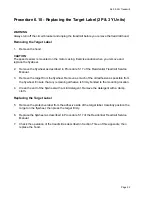
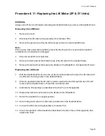
38. Calibrate the lift assembly as described in Procedure 4.1 of this appendix.
39. Check the operation of the treadmill as described in Section Three of this appendix, then
replace the hood as described in Procedure 5.1 of the Residential Treadmill Service
Manual.
Summary of Contents for 9.45
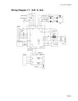
Page 55: ...9 45 9 45i Treadmill Page 55 Wiring Diagram 7 1 9 45 1L Unit...
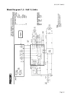
Page 56: ...9 45 9 45i Treadmill Page 56 Block Diagram 7 2 9 45 1L Units...
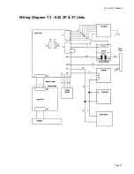
Page 57: ...9 45 9 45i Treadmill Page 57 Wiring Diagram 7 3 9 45 2P 3Y Units...
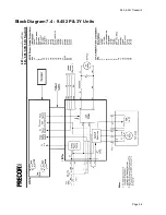
Page 58: ...9 45 9 45i Treadmill Page 58 Block Diagram 7 4 9 45 2P 3Y Units...

