background image

C546 Elliptical Fitness Crosstrainer

Page 110

7.

Insert the A.C. line cord in the power entry module and the A.C. outlet.

8.

Set the on/off switch in the on position and test the EFX per Section Four.

Summary of Contents for C546

Page 1: ...repair and maintain this product This document contains general product information software diagnostic procedures when available preventative maintenance procedures inspection and adjustment procedures troubleshooting procedures replacement procedures and electrical block and wiring diagrams To move directly to a procedure click the appropriate procedure in the bookmark section to the left of thi...

Page 2: ...CC CD and CE Version 3 was manufactured between August 2001 and the present The serial codes associated with version 3 are DC DE EX GT and GU Right Left Front and Back Conventions In this manual right left front and back are from the perspective of a user standing on the EFX 546 facing the display enclosure Warning and Caution Statements and General Safety Guidelines Warning statements indicate a ...

Page 3: ...event damage to the EFX as a result of the current activity Caution statements included in this manual are listed below Notice the orientation notch on the PROM These components must be positioned with the correct notch orientation When it is necessary to lift or move the EFX ensure that the EFX has adequate support and that you use proper lifting techniques Safety guidelines you should know and f...

Page 4: ...hat are not recommended by the manufacturer such attachments might cause injuries General Information On units manufactured prior to August 16 1998 a single lift connector J4 was used On subsequent units the lift motor wiring is in the J3 connector and the lift potentiometer wiring is in the J4 connector This text will use the connections used on current production units For units manufactured pri...

Page 5: ...airarms stairarm ramps and stairarm wheels using water or Simple Green Wipe the surface of the electronic console with a damp sponge or soft cloth Dry with a clean towel Simple Green is the only cleaning solution that has been tested and approved for use on the C546 ramps Use of any other cleaner may cause degradation of the ramp anodizing and void the ramp warranty The use of an acid citric based...

Page 6: ...maintenance activities Perform the software diagnostics Check LED and keypad function Record the odometer reading Check speed sensor function is the stride rate displayed when the unit is in operation If not see Procedure 6 4 Does the ramp lift operate smoothly and quietly If not see Procedure 6 5 Visually inspect the drive belts for cracks fraying or excessive wear Inspect the power cord If the p...

Page 7: ... with key 1 on the far left and key 7 on the far right The standard access codes use all sequential key presses The allowable delay between key presses is short If too much time is taken between key presses the access procedure will be aborted If the access is aborted it will be necessary to start over from the beginning See Diagram 3 1 Standard Access Codes Diagnostics Keys RESET 5 1 7 6 5 7 6 1 ...

Page 8: ... When you are familiar with the pattern it is easy to determine when a LED does not illuminate 4 If you do not observe the LED illumination sequences described in Step 3 THEN OTHERWISE Replace the upper PCA as described The LED test passed successfully in Procedure 7 2 or 7 3 continue with the next step 5 Power Bits will be displayed Power bits indicates the amount of power being applied to the ed...

Page 9: ...ss ENTER until seven dots illuminate in the left display window 10 Press each key listed below Verify that each single dot expands to four dots as the appropriate key is pressed ENTER Expands the far left dot CROSSRAMP DOWN Expands the second dot from the left CROSSRAMP UP Expands the third dot from the left STOP RESET Expands the center dot RESISTANCE DOWN Expands the third dot from the right RES...

Page 10: ...ay window column illuminates appropriately as each key is pressed THEN OTHERWISE The keypad test passed successfully Troubleshoot per Procedure 6 2 or 6 3 continue with the next step 12 End the keypad test by pressing the CROSSRAMP and RESISTANCE keys simultaneously ...

Page 11: ...ed Check to ensure that all of the LED s are illuminated 5 Press the ENTER key to continue to the next test 6 The message KEYBOARD TEST will be displayed 7 The display will light two dots for each key on the display When a key is pressed the upper of the two lights will go out Check each key position to ensure that all keys are functioning normally 8 Press and hold the ENTER key to continue to the...

Page 12: ...the incline position 14 The A D number should range between approximately 94 and 209 15 Press the ENTER key to continue to the next test 16 The message BRAKE TEST will be displayed 17 The display will the read LEVEL followed by the resistance level and BRAKE followed the the power bits number When the resistance level is changed the level should change and the power bits number brake should track ...

Page 13: ...eys RESET 6 5 sequentially until the message EFX 546 ODOMETER scrolls across the display window 3 Press ENTER then release Note The right display window displays the total strides on the EFX 546 see Diagram 3 2 The number displayed is 102 187 To convert strides to miles divide the total number of strides by 2241 To convert strides to kilometers divide the total number of strides by 1392 5 Diagram ...

Page 14: ...the software version and part number of the PROM will be displayed Note If you cannot determine the software version number in this manner look at the PROM mounted on the upper PCA A label on the PROM indicates the software version number 5 Press ENTER to exit ...

Page 15: ...Where XXXX is the total number of hours the unit has been in operation 8 Press the ENTER key to continue 9 The message SOFTWARE VERSION will be displayed 10 The display will then read UPPER X XX and LOWER X XX Where X XX is the software version number Both the upper PCA software version and lower PCA software version numbers are displayed 11 Press the ENTER key to continue 12 The message ERROR LOG...

Page 16: ...lowed to use the unit 4 The maximum workout time is adjustable between 10 and 240 minutes If you wish to change the maximum workout time THEN OTHERWISE Use the or keys to select Continue with the next step the new maximum workout time then continue with the next step 5 Press ENTER to continue 6 The pause time will be displayed The pause time is the length of time from the point that the PAUSE key ...

Page 17: ...d press the ENTER key to continue 8 The message SELECT MAXIMUM WORKOUT TIME will be displayed 9 Use the keys to select the maximum workout time to be displayed The maximum workout time sets the maximum amount of time the user can remain in a course 10 When the desired maximum workout time has been selected press the ENTER key to continue 11 The message SELECT MAXIMUM PAUSE TIME will be displayed 1...

Page 18: ...to Precor When a problem occurs record the following information Model and serial number Software version number Note Look at the PROM mounted on the upper PCA A label on the PROM indicates the software version number User and program number running when the problem occurred A description of a What happened or failed to happen b The action taken by the user just before the problem occurred c Probl...

Page 19: ...y troubleshoot per Section 6 7 Press the RESISTANCE key until you reach Resistance Level 10 Operate the EFX for another 2 3 minutes 8 If the EFX resistance does not change or the operation of the EFX feels inconsistent compared with Resistance Level 1 troubleshoot per Section 6 9 Press the RESISTANCE key until you reach Resistance Level 20 Operate the EFX for another 2 3 minutes 10 If the resistan...

Page 20: ... Fitness Crosstrainer Page 20 14 If the ramp system of the EFX 546 does not operate properly troubleshoot per Procedure 6 5 15 Turn off the EFX with the circuit breaker then unplug the power cord from the wall outlet ...

Page 21: ...the rear cover as described in Procedure 7 1 2 Set the ohmmeter to a range that will conveniently read up to 125 Ω 3 Disconnect the magnet wires Measure the resistance between the two magnet wires Note The resistance of the magnets will be higher than optimum 90 110 Ω when they are warm 4 If the resistance measures significantly less than 90 Ω or significantly more than 110 Ω THEN OTHERWISE Replac...

Page 22: ... cover and remove the front cover 4 Remove the four screws that retain the ramp end cap to the ramp assembly Support the lift motor and ramp assembly as you separate the ramp end cap from the ramp assembly Lower the ramp assembly until it is resting on the frame See Diagram 5 1 Diagram 5 1 Lift Motor Mounting 5 Do not remove the ramp end cap from the lift motor drive screw 6 Set the on off switch ...

Page 23: ...SRAMP or CROSSRAMP keys as required to set the lift calibration number to 139 12 Rotate the ramp end cap on the lift motor drive screw until the distance from the upper surface of the plastic nut in the ramp end cap to the end of the drive screw is 10 If the lift motor drive screw rotates the lift calibration number will no longer be 139 The lift calibration number must be 139 and the distance mea...

Page 24: ...tch in the on position Enter the diagnostics routine per Procedure 3 2 After the L E D test is complete power bits will be displayed Press the ENTER key to display the lift calibration number 5 Operate the CROSSRAMP or CROSSRAMP keys as required to set the lift calibration number to 127 6 Rotate the lift yoke on the lift motor drive screw until the distance from the upper surface of the plastic nu...

Page 25: ...d 8 Raise the ramp assembly to a convenient height and slide the lift yoke into the ramp assembly Hand tighten the four lift yoke mounting screws and then torque them to 240 in lbs 9 Set the on off switch in the on position Thoroughly test all lift related functions per Section Four 10 Set the on off switch in the off position replace the front cover per Procedure 7 1 ...

Page 26: ...Diagram 5 4 for the following belt alignment steps The right and left tension bolts have locking tabs If necessary use pliers to bend the locking tabs out of the way so that the bolts can be turned 7 If the step up pulley belt is out of alignment to the right continue with step 9 8 If the step up pulley belt is out of alignment to the left continue with step 11 9 Turn the left tension bolt 1 4 tur...

Page 27: ... edge along the length of the belt and beside the belt gauge Slide one of the o rings up against the shoulder of the belt gauge Press downward on the belt gauge causing the belt to deflect Read the deflection on the belt gauge at the edge of the straight edge Deflect the belt 1 4 Read the tension across the top edge of the o ring If the belt is correctly tensioned the gauge will read between 19 an...

Page 28: ...ter turn increments until the belt tensioning gauge reads 19 21 pounds 1 4 deflection 17 Verify that the belt alignment is still correct by performing the procedure in step 4 18 When both the step pulley tension and alignment are correct use pliers to bend the tension bolt locking tabs into the locking position 19 The input pulley tension must now be checked and corrected if necessary There is not...

Page 29: ...he stub tensioner axle nut slightly Turn the stub tensioner adjustment bolt clockwise to increase or counterclockwise to decrease the input belt tension 23 When the input belt tension is correct torque the stub tensioner nut to 200 in lbs Replace the stairarms per Procedure 7 24 24 Check the operation of the unit as described in Section Four then re install the rear cover as described in Procedure...

Page 30: ...on 1 units manufactured prior to Feb 8 1999 1 Set the on off switch in the off position WARNING Before continuing with this procedure review the Warning and Caution statements listed in Section One Things You Should Know 2 Attach the anti static wrist strap to your arm then connect the ground lead of the wrist strap to the units frame 3 Remove the interconnect cable cover See Diagram 7 2 4 Remove ...

Page 31: ...ocedure 7 7 If the unit does not operate properly continue with the next step 16 Reconnect the original lower interconnect cable to the lower PCA 17 Reconnect the lower interconnect cable to the upper interconnect cable 18 Replace the lower PCA shield 19 Replace the rear cover 20 Replace the interconnect cable cover 21 Check operation as described in Section Four Version 1 units manufactured after...

Page 32: ...ute the cable outside of the unit at this time 36 Check operation as described in Section Four 37 If the unit operated correctly when the new interconnect cable was installed the original interconnect cable is bad Install a new interconnect cable per Procedure 7 5 If the unit does not operate properly continue with the next step 38 Reconnect the original upper interconnect cable to the upper PCA T...

Page 33: ...C546 Elliptical Fitness Crosstrainerl Page 33 46 Replace the lower PCA shield 47 Replace the rear cover 48 Replace the interconnect cable cover 49 Check operation as described in Section Four ...

Page 34: ...in the off position WARNING Before continuing with this procedure review the Warning and Caution statements listed in Section One Things You Should Know 2 Remove the screws that secure the upper display assembly to the upper handrail Carefully pull some excess interconnect cable out from the targa upright Rotate the display housing so that the rear of the upper PCA is facing upward and set the dis...

Page 35: ... of J4 CROSSRAMP 0 Vdc and 500 mVdc Pin 5 of J4 CROSSRAMP 0 Vdc and 500 mVdc Pin 7 of J4 PAUSE 0 Vdc and 500 mVdc Pin 8 of J4 RESISTANCE 0 Vdc and 500 mVdc Pin 9 of J4 RESISTANCE 0 Vdc and 500 mVdc Pin 10 of J4 QUICK START 0 Vdc and 500 mVdc 7 If the voltage readings match those listed in Tables 6 1 and 6 2 and one or more keys do not function replace the upper PCA 8 If the voltage readings in Tab...

Page 36: ...trainer Page 36 13 Position the display enclosure on the display plate Install the screws that secure the display enclosure to the display plate 14 Check the operation of the treadmill as described in Section Three of this appendix ...

Page 37: ... static wrist strap to your arm then connect the ground lead of the wrist strap to the units frame 3 If the EFX powers up and functions normally until a particular key s is pressed skip to step 12 4 If a key depressed message is immediately displayed when the EFX is powered up continue with the next step 5 This condition may be caused by either the keypad or upper PCA Set the on off switch in the ...

Page 38: ...gnostics program per procedure 3 2 If the key s necessary to access the diagnostic program is not functioning skip to step 14 13 Test the keypad per Procedure 3 2 step 4 14 If all of the keys test good the problem may be user error or a key function that is normally disabled during a particular user program 15 If one or more keys do not function correctly either the keypad display housing or upper...

Page 39: ...e faces outward The magnet polarity may be checked with another magnet with known poles or a compass The north pole of the test magnet or the south facing needle should be attracted to the speed sensor magnet 3 Using a DC voltmeter measure the voltage between terminal 1 red wire and terminal 5 black wire on the speed sensor connector The measurement should be approximately 5 Vdc If the voltage is ...

Page 40: ...de rate is not displayed when the unit is operated there are three parts that could cause the problem There are not any good tests to check these parts other than substituting a known good part They are lower PCA ribbon cable and upper PCA Replace only one part at a time If the new part does not correct the problem replace the original part 8 If you have performed all of the above tests and the sp...

Page 41: ...ure 3 2 and proceed to the lift calibration portion of the diagnostics program If the lift calibration number is 0 or 255 skip to step 3 Operate the lift if the lift calibration number does not increment as the lift moves skip to step 3 If the calibration number increments as the lift moves re calibrate the lift per Procedure 5 3 If re calibration does not correct the problem continue with step 3 ...

Page 42: ...s If line voltage is not present skip to step 11 If line voltage is measured but the motor does not move replace the lift motor 10 Monitor terminals 1 and 3 white and black wires of J3 Enter the manual program and press the RAMP key The measurement should be approximately 120 Vac line voltage If the voltage is present and the lift motor moves normally skip to step 12 The voltage will only be prese...

Page 43: ...step 3 3 Set the on off switch in the off position Check the magnet wiring per Diagram 8 1 If any of the magnet wiring is reversed or incorrect the resistance will be affected If you have performed all of the above tests and there is still no resistance call Precor Technical Support 4 Set the on off switch in the off position Using an ohmmeter measure between the M and M terminals of the lower PCA...

Page 44: ...e are not any good tests to check these parts other than substituting a known good part They are lower PCA ribbon cable and upper PCA Replace only one part at a time If the new part does not correct the problem replace the original part 10 If you have performed all of the above tests and the resistances are still incorrect call Precor Technical Support ...

Page 45: ...he on off switch and the input module Replace any cut or nicked wiring 9 Check the line cord for nicked or cut wiring Replace the line cord if necessary 10 If you have performed all of the above tests and are unable to resolve the problem contact Precor customer support 11 Replace the F1 1 4 amp fuse in the lower PCA perform the resistance measurement in step 6 The reading should be approximately ...

Page 46: ... PCA If the reading is now good the problem is either the interconnect cable or the upper PCA 18 Substitute a known good upper PCA If the upper PCA does not correct the problem troubleshoot the upper and lower interconnect cables per Procedure 6 1 19 If you have performed all of the above tests and are unable to resolve the problem contact Precor customer support ...

Page 47: ...herwise continue with the next step 9 If the reading in step 5 is significantly low check the wiring between the lower PCA and the on off switch between the on off switch and the input module Replace any cut or nicked wiring 10 Check the line cord for nicked or cut wiring Replace the line cord if necessary 11 If you have performed all of the above tests and are unable to resolve the problem contac...

Page 48: ...h in the on position Repeat step 15 If the reading is still significantly low replace the lower PCA If the reading is now good the problem is either one of the interconnect cables or the upper PCA 19 Substitute a known good upper PCA If the upper PCA does not correct the problem troubleshoot the upper and lower interconnect cables per Procedure 6 1 20 If you have performed all of the above tests a...

Page 49: ...ing received the system will accept the hand held signal Note There are four typical failure modes for the hand held chest strap heart rate system They are 1 hand held is normal no chest strap reading 2 no hand held reading chest strap normal 3 no hand held or chest strap reading 4 constant or intermittent readings when neither hand held or chest strap are in use Diagram 6 3 Hand held chest strap ...

Page 50: ...ip to step 13 11 The source of the radiated energy must be determined and relocated so that it no longer affects the heart rate PCA Televisions cell phones Cardio theatre receivers etc are possible sources of radiated energy 12 Set the on off switch in the off position and remove the temporary jumper from J14 of the heart rate PCA Re locate all potential sources of radiation Set the on off switch ...

Page 51: ...l is being accepted measure between the ground and 5 Vdc pins on J4 for 5 Vdc If 5 Vdc is present replace the heart rate PCA 19 If 5 Vdc is not present remove the connector from J4 of the heart rate PCA Measure between the ground and 5 Vdc pins of the connector just removed from the heart rate PCA for 5 Vdc If 5 Vdc is present replace the heart rate PCA If the 5 Vdc is not present measure between ...

Page 52: ...er Page 52 25 Set the on off switch in the off position and remove the spare jumper from J14 of the heart rate PCA Re locate all potential sources of radiation Set the on off switch in the on position and repeat the procedure in step 6 ...

Page 53: ...cing the Rear Cover version 1 2 2 Remove the screws that secure the rear cover 3 Lift and slightly spread the rear cover until it clears the unit then set it aside 4 When maintenance operations are complete position the rear cover at its mounting position 5 Replace the screws that secure the rear cover Removing and Replacing the Front Cover version 1 2 6 Remove the screws that secure the bottom of...

Page 54: ... C outlet WARNING Before continuing with this procedure review the Warning and Caution statements listed in Section One Things You Should Know 14 The rear cover is a four piece cover front top left and right sections If the front cover section is being removed the frame cover must also be removed See Diagram 7 2 15 If you are removing either the right or left cover section it is only necessary to ...

Page 55: ...C546 Elliptical Fitness Crosstrainerl Page 55 section to the front cover section ...

Page 56: ...d fit the front cover against the frame cover Slide the front and frame covers into place as a unit Replace and tighten the four phillips screws that fasten the frame cover to the frame Replace and tighten the two phlliips screws that fasten the front cover section to the frame 21 Set the top cover section in it s mounting position replace and tighten the two phillips screws that fasten the top co...

Page 57: ...5 Remove the four upper front cover mounting screws two each side from the upper frame 26 Remove both front cover halves from the unit 27 When service is complete set both cover halves in their mounting positions 28 Replace the four upper front cover mounting screws two each side in the upper frame 29 Replace the four lower front cover mounting screws two each side in the lower frame ...

Page 58: ...e interconnect cover cable See Diagram 7 4 3 Remove the screws that secure the reading rack to the to the display backing plate Remove the reading rack 4 Remove the screws that secure the display housing to the display backing plate 5 Attach the wrist strap to your arm then connect the ground lead of the wrist strap to the EFX frame 6 Disconnect the interconnect cable from the upper PCA 7 If you a...

Page 59: ...13 Remove the ground lead of the wrist strap from the EFX frame then remove the wrist strap from your arm 14 Position the display enclosure on the display plate Replace and tighten the display mounting screws 15 Reposition the reading rack replace and tighten the reading rack mounting screws 16 Reposition the interconnect cable cover replace and tighten the interconnect cable cover mounting screws...

Page 60: ...hould Know 2 Attach the anti static wrist strap to your arm then connect the ground lead of the wrist strap to the units frame 3 Remove the four screws that secure the display housing front panel to the display backing plate 4 Attach the wrist strap to your arm then connect the ground lead of the wrist strap to the EFX frame 5 Disconnect the upper interconnect cable from the upper PCA connector J5...

Page 61: ...mounting screws 9 Reconnect the keyboard cable to the upper PCA 10 Reconnect the upper interconnect cable to the upper PCA 11 Remove the ground lead of the wrist strap from the EFX frame then remove the wrist strap from your arm 12 Position the display enclosure on the display plate Replace and tighten the display mounting screws 13 Check operation as described in Section Four Upper PCA Keyboard C...

Page 62: ...ackage PLCC44 Each of these packages should be removed with a proper IC removal tool see the illustrations below 4 The IC s may inserted into their socket by hand by carefully aligning the notch on the IC with the notch on the IC socket and carefully pressing the IC into its socket See the illustrations below for the alignment notches Care must be taken that the IC legs on a DIP28 are all aligned ...

Page 63: ... and Caution statements listed in Section One Things You Should Know 2 Remove the rear cover as described in Procedure 7 1 3 Attach the wrist strap to your arm then connect the ground lead of the wrist strap to the EFX frame 4 Remove the shield from the lower PCA 5 Disconnect the cables from the lower PCA 6 Remove the screws that secure the lower PCA Diagram 7 6 Lower PCA F2 1 4A Fuse F1 J3 J8 TP5...

Page 64: ...screws that secure the lower PCA 9 Connect the cables you disconnected in Step 5 10 Install the lower PCA shield 11 Remove the ground lead of the wrist strap from the EFX frame then remove the wrist strap from your arm 12 Re install the rear cover as described in Procedure 7 1 then check the operation of the EFX 546 as described in Section Four ...

Page 65: ...cedure review the Warning and Caution statements listed in Section One Things You Should Know 2 Remove the rear cover 3 Attach the wrist strap to your arm then connect the ground lead of the wrist strap to the EFX frame 4 Remove the shield from the lower PCA 5 Disconnect the cables from the lower PCA 6 Remove the screws that secure the lower PCA Diagram 7 7 Lower PCA D2 LED D7 LED J5 Connector F1 ...

Page 66: ...on 8 Install the screws that secure the lower PCA 9 Connect the cables you disconnected in Step 5 10 Install the lower PCA shield 11 Remove the ground lead of the wrist strap from the EFX frame then remove the wrist strap from your arm 12 Re install the rear cover then check the operation of the C556 as described in Section Four ...

Page 67: ...were used on the C546 Version 1 units manufactured prior to Feb 8 1999 used an upper and lower ribbon cable Version 1units manufactured after Feb 7 1999 used a single ribbon cable Version 2 3 units used an upper and lower telephone cable RJ45 For version 1 units manufactured prior to Feb 8 1999 start with step 3 For version 1 units manufactured after Feb 7 1999 start with step 20 For version 2 3 u...

Page 68: ...r Interconnect Cable 12 Remove the rear cover Remove the shield from the lower PCA Disconnect the interconnect cable from the lower PCA See Diagram 7 6 13 Lay the EFX on it s side The upper and lower interconnect cables are connected in the main frame tube Locate the access hole in the main frame tube See Diagram 7 8 14 Two cables are in the main frame tube The lift motor cable and the interconnec...

Page 69: ...nnect cable to the lower PCA 27 Replace the shield on the lower PCA Replace the rear cover 28 Check the operation of the EFX as described in Section Four Version 2 3 units 29 Loosen but do not remove the upper handrail clamp bolts 30 Remove the four screws that fasten the center handrail tube clamp See Diagram 7 24 31 Slowly rotate the center handrail tube forward to expose the cables in the cente...

Page 70: ...e existing lower interconnect cable 43 Carefully pull the interconnect cable out of the access hole near the lower PCA 44 Remove the tape and discard the old lower interconnect cable 45 Connect the lower interconnect cable to the lower PCA Replace the lower PCA shield Replace the rear cover 46 Using the mid point connector removed in step 31 connect the upper interconnect cable to the lower interc...

Page 71: ... 3 Remove the fuses from the fuse drawer and test them with an ohmmeter Both fuses should read approximately 1Ω or less If both fuses test good continue with step 4 If either fuse reads significantly high replace the fuse and retest the EFX It may not be necessary to replace the power entry module If the fuse blows again as soon as power is applied troubleshoot the EFX per Procedure 6 6 4 Remove t...

Page 72: ...nstall the screws that secure the power entry module to the EFX frame 8 Refer to appropriate wiring diagram in Section 8 and reconnect the wires removed in step 5 Replace the ground wire on the ground stud 9 Fasten the power entry module mounting bracket to the EFX frame with the screws removed in step 4 10 Remove the fuses from the fuse drawer of the defective input power module Check the fuses a...

Page 73: ...e removing a line filter on a Disconnect the line filter assembly from 120 volt unit the on off switch and J1 and J2 connectors on the lower PCA You are removing a line filter on a Disconnect the line filter assembly from 240 volt unit the on off switch and step down transformer 5 Remove the screws that secure the line filter Remove the filter from its mounting position Replacing the Line Filter 6...

Page 74: ...et away from the frame to gain access to the on off switch wiring 4 Disconnect the wiring from the on off switch 5 Depress the mounting tabs that secure the switch to its mounting bracket Remove the switch from its mounting position Replacing the ON OFF Switch 6 Make sure that the new on off switch is set to the off position Position the switch assembly so that the label is facing up Snap the swit...

Page 75: ...ift motor on a version unit substitute the word lift yoke for ramp end cap See Diagram 5 3 1 Set the on off switch in the off position Remove the front cover as described in Procedure 7 1 2 Remove the four screws that retain the ramp end cap or lift yoke to the ramp assembly Support the lift motor and ramp assembly as you separate the ramp end cap from the ramp assembly Lower the ramp assembly unt...

Page 76: ...Remove the clevis pin from the lift motor Diagram 7 11 Lift Motor Mounting 6 Remove the lift motor from the EFX Replacing the LIft Motor 7 Mount the replacement lift motor with the clevis and hitch pins Thread the ramp end cap or lift yoke onto the lift motor drive screw Reconnect the lift motor cable and carefully push the excess cable into the access hole Replace the leveller 8 Set the on off sw...

Page 77: ...the ramp end cap into the ramp assembly Hand tighten the four ramp end cap mounting screws and then torque them to 100 in lbs 11 On version 3 units raise the ramp assembly to a convenient height and slide the lift yoke into the ramp assembly Hand tighten the four lift yoke mounting screws and then torque them to 240 in lbs Diagram 7 12 Ramp End Cap or Lift Yoke Mounting 12 Set the on off switch in...

Page 78: ...rocedure 7 1 3 Remove the stairarm assembly as described in Procedure 7 24 Note Notice the position of the two crank arms When the crankarms are replaced they must be positioned so that they are 180 degrees opposing 4 Remove the 14 mm bolt that secures the crankarm to the input pulley shaft It will be necessary use a Pitman arm puller or 4 to 6 gear puller to remove the crankarm Do not use a hamme...

Page 79: ...ng bolt into the input pulley shaft Torque the nut to 300 in lbs 10 Replace the stairarm assembly as described in Procedure 7 24 11 If you are replacing both crankarm assemblies repeat steps 8 and 9 for the second crankarm assembly 12 Set the on off switch in the on position Use the unit and note whether the stride rate is being displayed If the stride rate is zero while the unit is being used the...

Page 80: ...be removed If you encounter a situation where a pillow block bearing is damaged and requires replacement the entire assembly consisting of eddy current disk input pulley and pillow block bearings must be replaced See Procedure 7 17 for replacement instructions 2 The pillow block bearings contains grease fitting It is recommended that the bearings be periodically checked and greased if necessary Di...

Page 81: ...nput pulley assembly and pillow block bearings The pillow block bearings are permanently attached to the input pulley shaft and can not be removed If you encounter a situation where the eddy current disk is damaged and requires replacement the entire assembly consisting of eddy current disk input pulley and pillow block bearings must be replaced See Procedure 7 17 for replacement instructions ...

Page 82: ... Procedure 7 17 steps 6 9 7 Carefully lay the EFX on it s side Remove the bolts that retain mounting plate for the input module and on off switch Swing the mounting plate away from the drive unit 8 Remove the left and right tension bolts locking tabs and brackets Slide the step up pulley assembly with both the step up and input belts out of the drive unit 9 Remove the input pulley belt Set the rep...

Page 83: ... Procedure 7 17 steps 6 9 7 Carefully lay the EFX on it s side Remove the bolts that retain mounting plate for the input module and on off switch Swing the mounting plate away from the drive unit 8 Remove the left and right tension bolts locking tabs and brackets Slide the step up pulley assembly with both the step up and input belts out of the drive unit 9 Remove the step up pulley belt Set the r...

Page 84: ...ribed in Procedure 7 20 6 Remove tension from the input pulley and step up pulley belts as described below a Loosen the stub tensioner axle nut and turn the stub tensioner adjustment nut counter clockwise until tension is removed from the input belt See Diagram 5 4 b Straighten the locking tabs and turn the left and right tension bolts counterclockwise until tension is removed from the step up bel...

Page 85: ...he input drive assembly to 500 inch pounds Diagram 7 16 Drive Unit Alignment 12 Place the input belt and step up belt in place on their pulleys Tighten both belts enough so that they don t slip and are roughly aligned The tensioning and alignment of the belts will be completed in a later step 13 Replace the magnet assembly per procedure 7 20 14 Complete the installation drive belt alignment and te...

Page 86: ...C546 Elliptical Fitness Crosstrainer Page 86 16 If the drive units was moved in step 15 re check the drive belt alignment and tensioning per Procedure 5 3 17 Replace the cover ...

Page 87: ...ft and right tension bolts locking tabs and brackets 9 Carefully lay the EFX on it s side Remove the bolts that retain mounting plate for the input module and on off switch Swing the mounting plate away from the drive unit 10 Slide the step up pulley assembly with both the step up and input belts out of the drive unit 11 Place the step up and input belts on the replacement step up pulley assembly ...

Page 88: ... in the correct crankarm or the speed sensor will not function 2 For version 1 2 units continue with step 3 For version 3 units skip to step 10 3 Remove the rear cover 4 Disconnect the speed sensor cable from the lower PCA See Diagram 7 17A Diagram 7 17A Speed Sensor Mounting version 1 2 5 Remove the mounting nut that secures the speed sensor assembly to the frame Thread the speed sensor out of th...

Page 89: ...res the speed sensor assembly to the frame Thread the speed sensor out of the frame Replacing the Speed Sensor Assembly 13 Thread the replacement speed sensor into the frame as far as possible Rotate the crankarm until the magnet in the crankarm is next to the speed sensor Thread the speed sensor out of frame as required to set the distance between the speed sensor and the magnet to 1 4 inch 14 Re...

Page 90: ...ion One Things You Should Know 2 Remove the rear cover 3 Disconnect the magnet cable from the magnet assembly 4 Remove the bolts that secure the magnet assembly to the drive unit Remove the magnet from the drive unit Diagram 7 18 Eddy Current Magnet Replacing the Magnet Assembly 5 Position the magnet assembly at its mounting position 6 Replace and hand tighten the magnet assembly mounting bolts To...

Page 91: ...ddy current magnet If not loosen the centering bolts see Diagram 7 18 and center the eddy current magnet on the eddy current disk Torque the centering bolts to 150 inch pounds 8 Reconnect the magnet cable to the magnet assembly 9 Re install the rear cover then check the operation of the EFX as described in Section Four ...

Page 92: ...he stairarm pivot has been made an integral part of the stairarm assembly The pivot block is no longer individually replaceable The stairarm is provided with a pivot block that is permanently attached to the stairarm If the pivot block is defective the stairarm must be replaced per Procedure 7 24 ...

Page 93: ...ings You Should Know 3 Because the replacement wheels are improved both the right and left wheel should be replaced Additionaly two new wheel covers 43702 504 will be required accomodate larger wheel mounting bolts 4 The wheel assembly is provided as an assembly that includes both wheels and replacement wheel axle screws Remove the four wheel cover mounting screws wheel cover from the stairarm and...

Page 94: ... from the wheel Discard the bolts and the wheel Replacement wheel mounting bolts are furnished with the replacement wheel 9 Install the replacement wheel assembly in the wheel cover Install and hand tighten the two wheel axle bolts Torque the wheel cover bolts to 15 foot pounds 10 Plug the power cord into the wall outlet set the on off switch in the on position and thoroughly test the operation of...

Page 95: ...om the wall outlet 2 Loosen and remove the two bolts that fasten the stairarm pedal onto the stairarm 3 Remove the stairarm pedal from the stairarm 4 Set the replacement stairarm pedal at it s mounting position on the stairarm 5 Install and hand tighten the stairarm pedal mounting hardware removed in step 2 Torque the stairarm pedal mounting bolts to 60 in lbs ...

Page 96: ... 6 Set the stairarm pedal at it s mounting position on the replacement stairarm 7 Install and hand tighten the stairarm pedal mounting hardware removed in step 5 Torque the stairarm pedal mounting bolts to 60 in lbs 8 Remove the four screws that fasten the wheel cover assembly to the stairarm Remove the wheel cover assembly from the stairarm 9 Install the wheel cover assembly on the replacement st...

Page 97: ...mbly toward the rear of the unit 4 If the ramp end cap is not being replaced do not allow the ramp end cap to rotate on the lift motor drive screw If the ramp end cap is rotated the lift motor must be re calibrated per Procedure 5 2 5 If only the ramp end cap is being replaced skip to step 13 Otherwise continue with the next step 6 Remove the ramp pivot block mounting screws from one of the ramp p...

Page 98: ...amp Assembly 10 Set the ramp track s in their mounting position on the ramp base thread and hand tighten the ramp track mounting screws Torque the ramp track mounting screws to 200 in lbs 11 If necessary mount one ramp pivot block onto the ramp assembly Be sure to orient the ramp pivot block so that the shoulder on the ramp pivot block faces inward Hand tighten the pivot block mounting screws and ...

Page 99: ...d then torque them to 120 in lbs 13 If ramp end cap has been replaced or the ramp end cap was rotated on the lift motor drive screw recalibrate the lift motor per Procedure 5 2 14 Align the ramp assembly with the ramp end cap and slide the ramp end cap into the ramp assembly 15 Thread and hand tighten the ramp end cap mounting screws and then torque them to 100 in lbs 16 Replace the front cover pe...

Page 100: ...drail clamp 3 Loosen the four set screws that fasten the lower end of the handrail into the frame tube 4 Slide the upper end of the handrail out of the upper handrail clamp and then slide the lower end of the handrail off of the frame tube 5 Slide the upper end of the replacement handrail into the upper handrail clamp and then insert the lower end of the handrail onto the frame tube mount 6 Tighte...

Page 101: ...crews that secure the interconnect cable cover to the bottom of the display backing plate Remove the interconnect cover cable See Diagram 7 4 6 Remove the screws that secure the reading rack to the to the display backing plate Remove the reading rack 7 Remove the screws that secure the display housing to the display backing plate 8 Disconnect the interconnect cable from the upper PCA 9 Remove the ...

Page 102: ...C546 Elliptical Fitness Crosstrainer Page 102 Diagram 7 23 Center Handrail Frame Tube Interconnect Cable Center Handrail Frame Tube Pin ...

Page 103: ...e lower clamp mounting screws See Diagram 7 24 Diagram 7 24 Clamp Mounting 14 Hold the display assembly in it s mounting position and reconnect the interconnect cable to the upper PCA 15 Position the display enclosure on the display plate Replace and tighten the display mounting screws 16 Reposition the reading rack replace and tighten the reading rack mounting screws 17 Reposition the interconnec...

Page 104: ...C546 Elliptical Fitness Crosstrainer Page 104 21 Repeat steps 19 and 20 for the other handrail 22 Check the operation of the EFX as described in Section Four ...

Page 105: ...move the rear cover as described in Procedure 7 1 3 Loosen the tension adjustment bolt to remove tension from the input belt See Diagram 7 25 Diagram 7 25 Stub Tensioner Mounting 4 The early C546 s mounted the stub tensioner in a closed slot If you have a unit with a closed slot it is recommended that the slot be cut open with a hacksaw Care must be taken not to cut the belt or other adjacent part...

Page 106: ... Remove the stub tensioner mounting nut and remove the stub tensioner from the drive unit 6 Loosely mount the replacement stub tensioner in it s mounting position 7 Complete the installation alignment and tensioning per Procedure 7 15 steps 11 to 15 ...

Page 107: ...r entry module 2 Remove the rear cover per Procedure 7 1 Diagram 7 27 Power Entry Module 3 Remove the blue wire from terminal D and the brown wire from terminal A of the power entry module 4 Remove the two screws that mount the power entry module to the rear cover support 5 Open the fuse compartment and remove both fuses See Procedure 7 30 Check both fuses with an ohmmeter They should read approxi...

Page 108: ...the screws removed in step 4 8 Replace the wires removed in step 3 Connect the blue wire to terminal D and the brown wire to terminal A of the power entry module 9 Replace the cover per Procedure 7 1 10 Insert the A C line cord in the power entry module and the A C outlet 11 Set the on off switch in the on position and test the EFX per Section Four ...

Page 109: ...d screwdriver carefully pry the fuse access door open See Diagram 7 28 Diagram 7 28 Power Entry Module Fuse 3 Using the thin bladed screwdriver carefully pry the fuse module out of the power entry module 4 The fuse module contains two fuses carefully pry one or both fuses out of the fuse module as required 5 Snap the replacement fuse s into the fuse module 6 Slide the fuse module back into the pow...

Page 110: ...C546 Elliptical Fitness Crosstrainer Page 110 7 Insert the A C line cord in the power entry module and the A C outlet 8 Set the on off switch in the on position and test the EFX per Section Four ...

Page 111: ...C546 Elliptical Fitness Crosstrainerl Page 111 Wiring Diagram 8 1 C546 120 Vac version 1 ...

Page 112: ...C546 Elliptical Fitness Crosstrainer Page 112 Block Diagram 8 2 C546 120 Vac version 1 ...

Page 113: ...C546 Elliptical Fitness Crosstrainerl Page 113 Wiring Diagram 8 3 C546 240 Vac version 1 AC Line Filter Step Down Transformer BL BL BL BL BL BR BR BR BR BR J3 ...

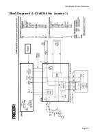
Page 114: ...C546 Elliptical Fitness Crosstrainer Page 114 Block Diagram 8 4 C546 240 Vac version 1 ...

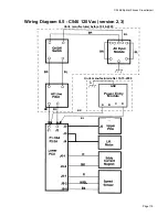
Page 115: ...Elliptical Fitness Crosstrainerl Page 115 Wiring Diagram 8 5 C546 120 Vac version 2 3 Power Entry Module BR BL GND A B C D BR BL G BL Units manufactured before 10 16 2000 Units manufactured after 10 15 2000 ...

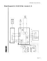
Page 116: ...C546 Elliptical Fitness Crosstrainer Page 116 Block Diagram 8 6 C546 120 Vac version 2 3 ...

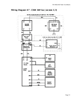
Page 117: ...Elliptical Fitness Crosstrainerl Page 117 Wiring Diagram 8 7 C546 240 Vac version 2 3 BL Units manufactured before 10 16 2000 BR BL Power Entry Module A B C D GND G BR BL Units manufactured after 10 15 2000 ...

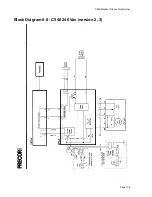
Page 118: ...C546 Elliptical Fitness Crosstrainer Page 118 Block Diagram 8 8 C546 240 Vac version 2 3 ...

Reviews: