C546 Elliptical Fitness Crosstrainerl
Page 71
Procedure 7.8 - Replacing the Power Entry Module
(version 1,2 units manufactured before 10-16-2000)
Removing the Power Entry Module
1.
Set the on/off switch in the off position, then unplug the power cord from the wall outlet and
from the EFX.
WARNING
Before continuing with this procedure, review the Warning and Caution statements listed in
Section One, Things You Should Know.
2.
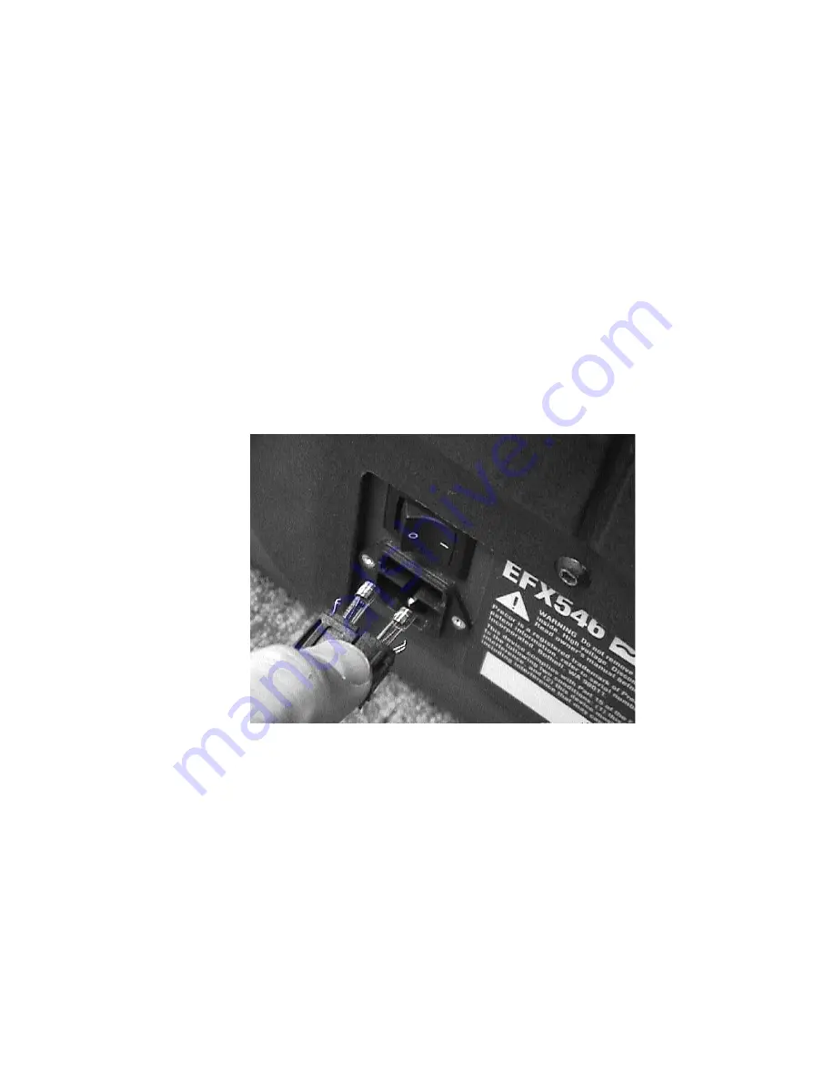
Release the fuse drawer from the power entry module. Remove the fuse drawer.
(See Diagram 7.9)
Diagram 7.9 - Fuse Drawer, Power Entry Module
3.
Remove the fuses from the fuse drawer and test them with an ohmmeter. Both fuses should
read approximately 1
Ω
or less. If both fuses test good, continue with step 4. If either fuse
reads significantly high, replace the fuse and retest the EFX. It may not be necessary to
replace the power entry module. If the fuse blows again as soon as power is applied,
troubleshoot the EFX per Procedure 6.6.
4.
Remove two screws from the bottom of the EFX frame that secure the power entry module
mounting bracket to the frame. Swing the power entry module mounting bracket away from
the frame to gain access to the on/off switch wiring.
5.
Remove the wires from the power entry module, a brown and blue wire, a brown and blue
jumper. Remove the ground wire from the ground stud.
Summary of Contents for C546
Page 55: ...C546 Elliptical Fitness Crosstrainerl Page 55 section to the front cover section ...
Page 111: ...C546 Elliptical Fitness Crosstrainerl Page 111 Wiring Diagram 8 1 C546 120 Vac version 1 ...
Page 112: ...C546 Elliptical Fitness Crosstrainer Page 112 Block Diagram 8 2 C546 120 Vac version 1 ...
Page 114: ...C546 Elliptical Fitness Crosstrainer Page 114 Block Diagram 8 4 C546 240 Vac version 1 ...
Page 116: ...C546 Elliptical Fitness Crosstrainer Page 116 Block Diagram 8 6 C546 120 Vac version 2 3 ...
Page 118: ...C546 Elliptical Fitness Crosstrainer Page 118 Block Diagram 8 8 C546 240 Vac version 2 3 ...


