C546 Elliptical Fitness Crosstrainer
Page 84
Procedure 7.17 - Replacing the Input Drive Assembly
1.
Set the on/off switch in the “off” position, then unplug the power cord from the wall outlet.
WARNING
Before continuing with this procedure, review the Warning and Caution statements listed in
Section One, Things You Should Know.
2.
Remove the rear cover.
3.
Remove the stairarm assemblies as described in Procedure 7.24.
4.
Remove the crankarm assemblies as described in Procedure 7.12.
5.
Remove the magnet assembly as described in Procedure 7.20.
6.
Remove tension from the input pulley and step-up pulley belts as described below:
a.
Loosen the stub tensioner axle nut and turn the stub tensioner adjustment nut counter-
clockwise until tension is removed from the input belt. (See Diagram 5.4)
b.
Straighten the locking tabs and turn the left and right tension bolts counterclockwise until
tension is removed from the step up belt. (See Diagram 5.2)
c.
Slide the input and step up belts off of their pulleys.
7.
Remove the stub tensioner per procedure 7.28, steps 4 and 5.
8.
Remove the input drive assembly mounting bolts (2 per pillow block bearing).
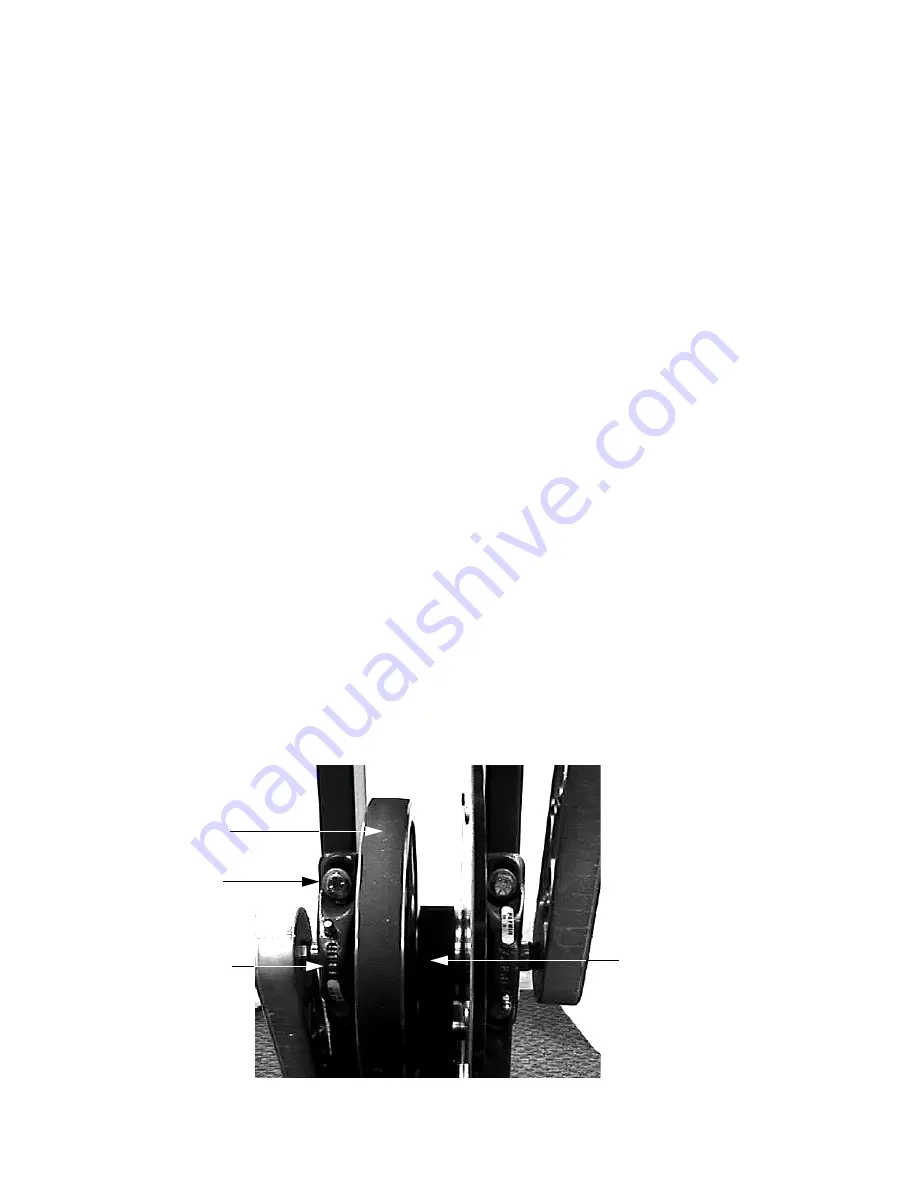
Diagram 7.15 - Input Drive Assembly
Mounting Bolt
Pillow Block
Input Pulley Belt
Step Up Pulley Belt
Summary of Contents for C546
Page 55: ...C546 Elliptical Fitness Crosstrainerl Page 55 section to the front cover section ...
Page 111: ...C546 Elliptical Fitness Crosstrainerl Page 111 Wiring Diagram 8 1 C546 120 Vac version 1 ...
Page 112: ...C546 Elliptical Fitness Crosstrainer Page 112 Block Diagram 8 2 C546 120 Vac version 1 ...
Page 114: ...C546 Elliptical Fitness Crosstrainer Page 114 Block Diagram 8 4 C546 240 Vac version 1 ...
Page 116: ...C546 Elliptical Fitness Crosstrainer Page 116 Block Diagram 8 6 C546 120 Vac version 2 3 ...
Page 118: ...C546 Elliptical Fitness Crosstrainer Page 118 Block Diagram 8 8 C546 240 Vac version 2 3 ...


