C554i Self Powered Elliptical Fitness Crosstrainer
Page 50
9.
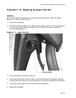
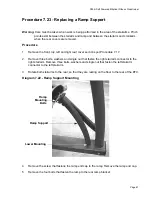
Unthread the right hand upper pivot from the main column with a 7/16” allen wrench. A 7/16”
hex key bit that fits your torque wrench will be required in step 16. Rotate the handlebar with
upper pivot forward until it rests on the floor.
10. Repeat the procedure in step 9 with the left hand upper pivot and handlebar.
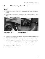
11. Remove the left and right frame tube per Procedure 7.22, steps 1-4.
12. Remove the two bolts and washers that fasten the bottom of the main column to the frame
base. Remove the main column.
13. Feed the upper interconnect cable into the replacement main column so that an end of the
cable protrudes from both ends of the main column.
14. Set the main column at it’s mounting location with the lower end of the upper interconnect
cable in the access hole in the frame base. Replace bolts and washers removed in step 12
and torque them to 240 in./lbs.
15. Replace the left and right frame tubes per Procedure 7.22, steps 5-7.
16. Rotate the right hand handlebar with upper pivot into it’s mounting position. Thread the
upper pivot into the main column and torque it to 100 ft./lbs.
17. Repeat the procedure in step 16 with the left hand handlebar and upper pivot.
18. Replace the cover with the hardware removed in step 8.
19. Connect the lower end of the upper interconnect cable to the mid-point connector. Careful
push the mid-point connector and cables into the frame tube. Replace the end cap.
20. Feed the upper end of the upper interconnect cable through access hole in the display
housing backplate. Set the display housing backplate at it’s mounting position and fasten it
with the screws removed in step 5.
21. Connect the upper interconnect cable to the J5 connector on the upper PCA. Set the display
housing front panel at it’s mounting location and fasten it with the hardware removed in step
3.
22. Replace the red battery lead removed in step 1 and check unit operation as described in
Section Four.

