page 17
C
O
M
M
E
R
C
I
A
L
P
R
O
D
U
C
T
S
D
I
V
I
S
I
O
N
13.
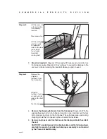
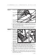
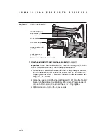
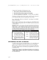
Connect the heart rate cables.
Diagram 12. Cables protrude from the ends of
both handrails and connect the metal strips on the handrails to the receiver
inside the display. Once the cables are properly connected, a user’s heart rate
appears when the user grasps both touch-sensitive grips.
Important:
Attach one cable at a time. The cable receptacles mirror the con-
nectors so that they cannot be improperly installed. Do not force a connection!
Take time to look for the appropriate cable receptacle. Perform the following
steps, one cable connection at a time.
a. Slide the end of the cable into its receptacle. Diagram 12, #1.
b. Place the excess cable inside the display opening. Diagram 12, #2.
c. Move to the opposite handrail and complete steps a and b.
14.
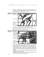
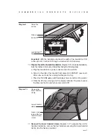
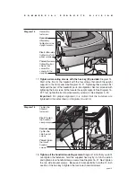
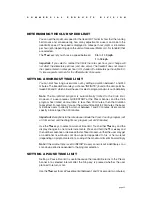
Test the heart rate feature.
Diagram 13.
a. Turn the unit ON. The Precor banner should appear in the display.
b. Face the display and straddle the running belt.
Diagram 12
Connect the
heart rate
cables.
Display console
Heart rate cable
connections (male
connector, female
receptacle and
vice versa for the
opposite cable)
Security clip
Left handrail
1
2
Diagram 13
Test the heart
rate feature.
Heart rate
grips
Display
console
Heart rate
blinking
indicator
IME
NCE
RIES
LINE
PROFILE
CALORIES/MINUTE
METS
SPEED
Hr

