background image

Pulldown Assembly Guide: Assembling the Equipment 

14 


Connecting the Gas Spring 

The gas spring, which lifts the seat assembly when an exerciser adjusts the 

seat height, is attached to the seat assembly and the frame through two 

ball-shaped stems. the underside of the seat assembly; the other is on the 

center upright near the base frame. 

To attach the gas spring: 

1.


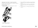
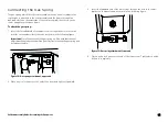
Insert the threaded end of the upper stem through the hole in the small 

bracket on the underside of the seat, as shown in the following figure. 

Important:

 Place the wide end of the gas spring up. Also, note that the seat 

adjustment handle has been omitted from this figure to keep the gas spring and 

its fasteners visible. 


Figure 12: Gas spring attachment, upper end 

2.


Place a nylon lock nut over the end of the stem and tighten it partially. 

3.


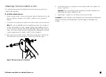
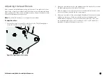
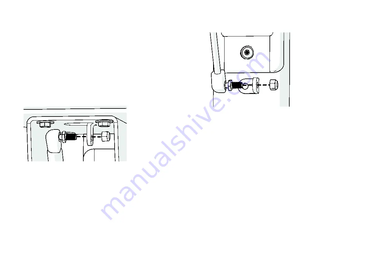
Insert the threaded end of the lower stem through the hole in the small 

bracket on the base frame, as shown in the following figure. 


Figure 13: Gas spring attachment, lower end 

4.


Place a nylon lock nut over the end of the lower stem. Tighten both nylon 

lock nuts completely. 

Summary of Contents for Discovery Plate Loaded Pulldown Series

Page 1: ...Manual do propriet rio Discovery Plate Loaded Line...

Page 2: ......

Page 3: ...rf cie s lida O equipamento foi desenvolvido para ser autossuficiente no entanto ele pode ser fixado ao ch o com parafusos para obter estabilidade adicional A Precor recomenda que o equipamento seja f...

Page 4: ...es poder o provocar acidentes pessoais Vista roupas e cal ados adequados para seu exerc cio n o roupas largas N o se exercite em excesso nem se esforce at a exaust o Fa a um julgamento sensato ao trab...

Page 5: ...ncia t cnica 5 Inspe o di ria 6 Limpar o estofamento 6 Inspecionar os protetores de uso 6 Limpar e examinar as estruturas 6 Verificar as etiquetas de instru es e avisos 7 Inspe o semanal 9 Manter o es...

Page 6: ...o da Precor Muitas pe as s o testadas e fabricadas especialmente para equipamentos de muscula o comerciais da Precor Se voc utilizar pe as n o aprovadas pela Precor a Garantia Limitada da Precor pode...

Page 7: ...ara estabelecer o modelo e o ano do produto Geralmente poss vel encontrar o n mero de s rie embaixo do suporte de assento Para futura refer ncia escreva os n meros de s rie os n meros do modelo e as d...

Page 8: ...m nia ou petr leo Use um produto de limpeza base de detergente neutro Inspecionar os protetores de uso Inspecione os protetores para o caso de rachaduras no estofamento grampos soltos e parafusos de s...

Page 9: ...ou se parte da etiqueta n o estiver pregada adequadamente substitua a imediatamente consulte Assist ncia t cnica para informa es de compra Quando necess rio limpe as etiquetas com uma solu o de sab o...

Page 10: ...m v rias etiquetas de aviso padr o As duas figuras a seguir mostram exemplos de etiquetas de aviso que podem ser vistas nos equipamentos dependendo do modelo e a linha do produto Figura 2 Etiqueta de...

Page 11: ...ecor recomenda o uso de uma pequena quantidade de lubrificante de silicone em spray para lubrificar essas buchas que geralmente d o suporte a eixos girat rios Aplique o spray diretamente no eixo e em...

Page 12: ...o fina Fa a o acabamento com o retoque de pintura da Precor se necess rio Mantenha a pintura lustrada com uma aplica o de cera automotiva suave Para preservar as pinturas a p e as partes cromadas uti...

Page 13: ...Manual do propriet rio Discovery Plate Loaded Line Observa es 11 Observa es...

Page 14: ...Manual do propriet rio Discovery Plate Loaded Line Observa es 12 Observa es...

Page 15: ......

Page 16: ...a intensamente patentes nos EUA e no exterior tanto para a constru o mec nica quanto para os aspectos visuais dos seus produtos Qualquer parte que contemple a utiliza o dos designs dos produtos da Pre...

Page 17: ...Assembly Guide Discovery Plate Loaded Line Pulldown...

Page 18: ......

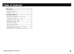
Page 19: ...ide Uprights to the Base Frame 9 Installing the Crossbar 9 Installing the Center Upright Assembly 10 Installing the Movement Arms 11 Attaching the Knee Roller Pads 12 Attaching the Seat Pad 13 Connect...

Page 20: ...ay from walls or furniture on either side of the equipment and 40 inches 1 meter away from objects behind the equipment Set up the unit on a solid flat surface so that it remains level and stable A le...

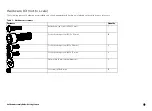
Page 21: ...hrink wrapped card Each part is labeled on the card for easy reference Table 1 Hardware kit contents Fasteners Quantity Buttonhead cap screw M8 x 15 mm 1 Socket head cap screw M12 x 35 mm 16 Socket he...

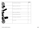
Page 22: ...eners Quantity Flat washer 13 mm internal diameter 16 Flat head cap screw M10 x 25 mm 2 Hex head cap screw inch x 1 inch 4 Flat head cap screw M6 x 30 mm 4 Flat washer 11 mm internal diameter 2 Socket...

Page 23: ...Started 5 Fasteners Quantity Roller end cap 2 Flat head cap screw M12 x 30 mm 6 inch nylon lock nut 2 Table 2 Other Equipment Parts Part Quantity Roller bar 1 Weight horn 2 Weight storage horn 4 Arm p...

Page 24: ...Pulldown Assembly Guide Getting Started 6 Part Quantity Weight horn end cap 2 Weight storage horn bumper 4 Gas spring 1 Instructional placard 1...

Page 25: ...u are instructed to do so Make sure the equipment is stable and placed on a solid surface The equipment is designed to be freestanding but it can be bolted to the floor for extra stability Precor high...

Page 26: ...the following figure Pull out the end cap then set the cap and the screws aside Figure 2 End cap removal 3 Using an open end wrench turn the jam nut to the left to loosen it 4 Using the same open end...

Page 27: ...ners Figure 4 Side upright attachment Installing the Crossbar Note Have your assistant hold the crossbar in place while you perform this procedure To attach the crossbar to the side uprights 1 Positio...

Page 28: ...ame and against the crossbar as shown in the following figure Figure 6 Center upright assembly 2 Place two M12 x 35 mm socket head cap screws and two 13 mm flat washers into the screw holes in the bas...

Page 29: ...e If the axle becomes jammed during this step check to make sure the movement arm and the bracket are still aligned If the axle remains jammed remove it and contact Customer Support 3 Place an axle mo...

Page 30: ...M8 x 6 set screw into each screw hole and tighten screws completely Figure 8 Set screw attachment 3 Slide a knee roller pad and one end cap onto the roller bar and secure it with one M6 x 30 flat hea...

Page 31: ...he seat pad 1 Position the pad over the seat bracket so that the screw holes in the seat and the bracket line up Figure 10 Seat position 2 Insert four inch x 1 inch hex head screws with 9mm flat washe...

Page 32: ...racket on the underside of the seat as shown in the following figure Important Place the wide end of the gas spring up Also note that the seat adjustment handle has been omitted from this figure to ke...

Page 33: ...he following figure shows the location of one of these screws Figure 14 Upper front roller location 2 Have your assistant press the seat pad down until the back roller contacts the black plastic plate...

Page 34: ...y 4 Insert two M8 x 6 mm set screws into the screw holes on the weight horn fitting Tighten the set screws completely 5 Slide a bumper down over the weight horn until it rests against the movement arm...

Page 35: ...screw then holds it in place To attach the instructional placard 1 Remove the protective backings from the machine name label Attach the label carefully to the recess at the upper front of the placard...

Page 36: ...the bracket as shown in the following figure Tighten the screw completely Figure 19 Securing the placard in place Note If you are installing labels in a language other than English remove the general...

Page 37: ...Pulldown Assembly Guide Notes 19 Notes...

Page 38: ...Pulldown Assembly Guide Notes 20 Notes...

Page 39: ......

Page 40: ...g designs of exercise equipment Precor aggressively seeks U S and foreign patents for both the mechanical construction and the visual aspects of its product design Any party contemplating the use of P...

Reviews: