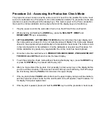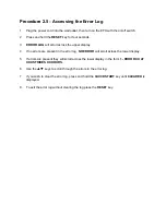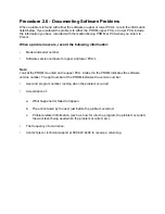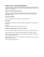
Procedure 5.1 - Measuring the Resistance of an Eddy Current
Magnet
Caution
Remove power from the EFX before you measure magnet resistance.
Procedure
1.
Set the on/off switch in the “off” position, then unplug the power cord from the wall outlet.
WARNING
Before continuing with this procedure, review the Warning and Caution statements listed in
Section One, Things You Should Know.
1.
Remove the left and right side rear covers as described in Procedure 7.1.
2.
Set the ohmmeter to a range that will conveniently read up to 125
Ω
.
3.
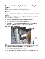
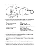
Disconnect the J1 (magnet) connector from the lower PCA. Measure the resistance
between the two terminals of the connector removed from the lower PCA.
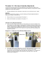
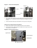
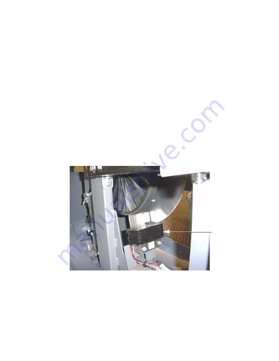
Diagram 5.1 - Eddy Current Magnet
Note:
The resistance of the magnets will be higher than optimum (90 - 110
Ω
) when they are warm.
4.
If the resistance measures significantly low or open, replace the magnet.
5.
Re-install the rear covers as described in Procedure 7.1.
6.
Set the on/off switch in the “on” position. Thoroughly test all functions per Section Four.
Eddy
Current
Magnet
Summary of Contents for EFX EFX 5.23
Page 79: ...Block Diagram 8 2 5 23 5 25...

