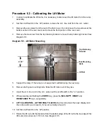
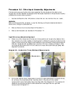
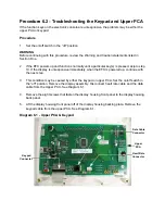

Procedure 5.3 - Calibrating the Lift Motor
1.
In order to calibrate the lift motor, it is necessary to disconnect the lift motor from the ramp
assembly.
2.
Set the on/off switch in the “off” position, remove the A.C. line cord from the A.C. outlet.
3.
Remove the six screws from the rear of the front cover. Do not remove the two screws at the
bottom center of the rear cover and remove the front portion of the rear cover.
4.
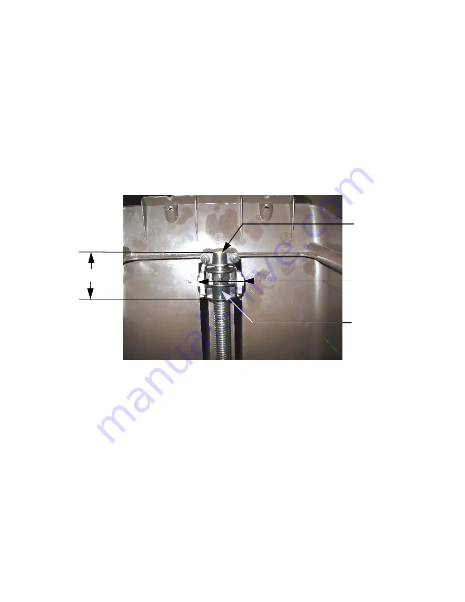
Remove the two screw from the top retaining bracket, remove the top retaining bracket. See
Diagram 5.5.
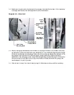
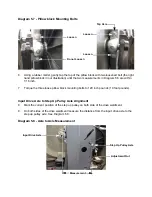
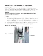
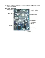
Diagram 5.5 - Lift Motor Mounting
5.
Support the ramp. If the ramp is not supported it will fall during the next step.
6.
Remove both yoke mounting bolts. Slide the lift motor out of the yoke.
7.
Insert the A.C. line cord in the A.C. outlet, set the on/off switch in the “on” position.
8.
While pressing and holding the
ENTER
key, press the
INCLINE
T
,
RESET
and
RESISTANCE
T
keys, sequentially.
9.
LIFT CALBRATION - LIFT MOVING TO LEVEL 8
will scroll across the lower display and
the incline will move to level 8, if it is not currently at level 8.
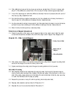
10. Set the on/off switch in the “off” position.
11. Rotate the lift nut until the distance from the bottom edge of the lift nut to the top edge of the
lift motor drive screw is 2-1/8 inch. See Diagram 5.5.
Top Retaining
Bracket
Yoke Mounting
Bolts
Lift Nut
2-1/8”
Summary of Contents for EFX EFX 5.23
Page 79: ...Block Diagram 8 2 5 23 5 25...


