3.
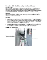
Rotate the step up pulley so that the speed sensor magnet is not near the speed sensor.
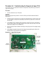
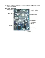
Using a DC voltmeter, measure the voltage between terminal 2 and terminal 6 of J7 on the
lower PCA. The measurement should be approximately 5 Vdc. See Diagram 6.5. If the
measurement is correct, skip to step 4. If the voltage is missing or significantly low,
disconnect the speed sensor and repeat the voltage measurement on the J7 on the lower
PCA. If the measurement is now correct (5 Vdc), replace the speed sensor. If the voltage is
still missing or significantly low, replace the lower PCA. Skip to step 5.
4.
Rotate the step up pulley so that the speed sensor magnet is next to the reed switch. Using
a DC voltmeter, measure the voltage between terminal 2 and terminal 6 of J7 on the lower
PCA. The measurement should be approximately 0 Vdc. If the voltage is 5 Vdc or
significantly high, replace the speed sensor per Procedure 7.12. Skip to step 8.
5.
With the an ohmmeter connected to terminals 2 and 6 of J7 on the lower PCA, rock the step
up disk forward and backward so that the magnet is passing in front of and away from the
reed switch. The ohmmeter should alternate between continuity (very low resistance) and
infinity (open circuit). If the resistance measurement does not alternate between continuity
and infinity, repeat steps 2 through 4. If the resistance does alternate between continuity
and infinity, continue with step 6.
6.
If you have performed all of the above tests and the stride rate is not displayed when the unit
is operated, there are two parts that could cause the problem. There are not any good tests
to check these parts other than substituting a known good part. They are lower PCA and the
upper PCA. Replace only one part at a time. If the new part does not correct the problem,
replace the original part.
7.
If you have performed all of the above tests and the speed sensor is still not functioning, call
Precor Technical Support.
8.
Check the operation of the EFX as described in Section Four.
Summary of Contents for EFX EFX 5.23
Page 79: ...Block Diagram 8 2 5 23 5 25...

