7.
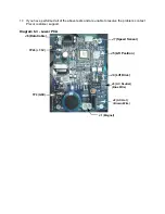
Set the on/off switch in the “on” position, enter the manual program and set the resistance at
level 10. Using a DC voltmeter, check the voltage across the magnet. wires at the lower
PCA The voltage should measure approximately 25 Vdc.
8.
If the voltage is still significantly high or low, there are two parts that could cause the
problem. There are not any good tests to check these parts other than substituting a known
good part. They are lower PCA and upper PCA. Replace only one part at a time. If the new
part does not correct the problem, re-install the original part.
9.
Set the on/off switch in the “off” position. Using an ohmmeter, measure between the magnet
wires at the lower PCA. The measurement should be approximately 90
Ω
to 110
Ω.
If the
measurement is significantly low, check the connections at both magnets and the lower
PCA.
10. With an ohmmeter, measure between each magnet wire and frame ground. A normal
reading for both measurements is open (
∞
). If the resistance is significantly low, disconnect
the J2 connector from the lower PCA and the eddy current magnet.
11. If you have performed all of the above tests and the resistances are still incorrect, call
Precor Technical Support.
Summary of Contents for EFX EFX 5.23
Page 79: ...Block Diagram 8 2 5 23 5 25...

