Procedure 6.5 - Upper Display does not Illuminate
1.
Set the on/off switch in the “off” position, unplug the line cord from the wall outlet.)
2.
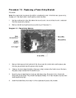
Remove the fuses from the power entry module. (See Procedure 7.5)
3.
Check all of the fuses with an ohmmeter. They should read approximately 1
Ω
or less.
Replace any fuse that reads significantly high.
4.
Replace the fuses in the power input module.
5.
With the line cord still unplugged from the wall outlet, set the on/off switch in the “on”
position. Check between the power terminals of the line cord with an ohmmeter. The
ohmmeter should read 1 to 1.5 megohm.
6.
If the reading is good, skip to step 11, if the reading is significantly low, continue with the
next step
7.
If the reading in step 5 is significantly low, check the wiring between the lower PCA and the
on/off switch, between the on/off switch and the input module. Replace any cut or nicked
wiring.
8.
Check the line cord for nicked or cut wiring. Replace the line cord if necessary.
9.
If the reading in step 5 is significantly low, replace the lower PCA
10. If you have performed all of the above tests and are unable to resolve the problem, contact
Precor customer support.
11. Plug the line cord into the wall outlet and set the on/off switch in the “on” position.
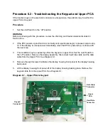
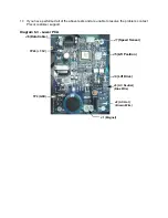
12. Measure between terminals 2 & 3 (white and violet wires) of the HR output connector on the
HR PCA with a DC voltmeter. See Diagram 6.3. The reading should be approximately 5.0
Vdc.
13. If the reading in step 12 is good, replace the upper PCA. If the reading in step 12 is
significantly low, set the on/off switch in the “off” position. Disconnect the data cable from the
upper PCA.
14. Set the on/off switch in the “on” position.
15. Measure between TP26 and TP2 on the lower PCA with a DC voltmeter. See Diagram 6.3.
The reading should be approximately 7.5 Vdc. if the measurement is good, replace the
upper PCA. If the measurement is significantly low, continue with step 16.
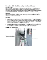
16. Disconnect the speed sensor cable from the lower PCA and repeat the measurement in
step 15. If the measurement is good, replace the speed sensor. If the measurement is
significantly low, replace the data cable.
Summary of Contents for EFX EFX 5.23
Page 79: ...Block Diagram 8 2 5 23 5 25...

